
JST GH vs PH: Which Connector Fits Your Cable Assembly?
Table of Contents
JST GH and PH are different wire-to-board connector systems. GH has a finer pitch and an external positive latch; PH uses a larger pitch and a different mating interface. Neither is a drop-in replacement for the other. For an existing board, identify its header first. For a new design, compare the complete connection: mating parts, wire, routing space, assembly process and operating conditions.
Quick choice: review GH when compact circuit spacing and an accessible positive latch suit the design. Review PH when its larger interface, available wire/contact combinations and board-mount options suit the design. A series name alone does not specify a finished harness.
GH vs PH at a glance
These are original JST catalog reference values, checked on 29 September 2026. They are not a rating for every wire option, a completed Zeakka assembly or an alternative connector.
| Item | JST GH | JST PH |
|---|---|---|
| Contact pitch | 1.25 mm | 2.00 mm |
| Retention structure | External positive latch | Different retention geometry; not the same external latch system |
| Standard housing range in the cited catalog | 2–15 circuits | 2–16 circuits |
| Catalog current rating | 1 A AC/DC with AWG 26 | 2 A AC/DC with AWG 24 |
| Catalog voltage rating | 50 V AC/DC | 100 V AC/DC |
| Catalog temperature range | −40 to +105 °C, including current-induced temperature rise | −40 to +105 °C, including current-induced temperature rise |
| Standard contact example | SSHL-002T-P0.2: AWG 30–26; insulation OD 0.76–1.00 mm | SPH-002T-P0.5S: AWG 30–24; insulation OD 0.8–1.5 mm |
| Smaller-wire contact example | Check the specified GH contact | SPH-004T-P0.5S: AWG 32–28; insulation OD 0.5–0.9 mm |
| Housing example | GHR-04V-S | PHR-4 |
| Board-side choices shown | SMT, top and side entry | Through-hole and SMT, top and side entry |
Sources: JST GH catalog, pages 1–3; JST PH catalog, pages 1–3. Confirm current drawings and full ordering suffixes before release.
Do not interpret the current row as “every PH harness carries twice the current.” Specify load, ambient temperature, populated circuits and duty cycle, then validate the selected assembly. Likewise, do not use a connector's catalog temperature range as the temperature rating of its cable insulation.
Browse GH-series alternative connectors, PH-series alternative connectors. These product pages cover alternatives; select the exact housing, contact and mating interface for your application.
Identify the connector before comparing replacements
Start with the PCB header reference, equipment drawing or approved bill of materials. If only a sample is available, record circuit count, contact-center spacing, mating face, polarizing features and wire exit direction. Photograph both the housing and the board-side header. A white housing or a seller's generic “JST cable” label does not establish the series.
Measure between contact centers rather than across the plastic body. For a four-position connector, the first-to-last center distance spans three pitches: 3.75 mm for GH and 6.00 mm for PH. This is a useful screening check, not sufficient proof of identity.
GH's external latch must engage and remain accessible for release. PH does not use the same external positive-latch geometry. Compare the actual mating pair instead of judging retention from a single photograph. Do not infer vibration qualification from a latch, or force a housing that appears almost compatible.
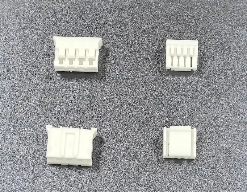
Alternative housings for the GH and PH series. Shown for visual comparison; original JST catalog specifications do not rate these samples.
Why GH and PH do not interchange
The difference extends beyond pitch. The housing, contacts, header and PCB footprint must form the intended mating system. Reusing a PH terminal in a GH housing, swapping only the cable-side housing or bending contacts to make a connection is not an acceptable substitution.
Changing series on a new revision usually requires a coordinated review of the board header, PCB layout, harness bill of materials, crimp process, enclosure clearance and inspection drawing. Carry the electrical pin mapping through the revision explicitly; a matching circuit count does not prove matching polarity.
A GH-to-PH cable can connect two different, correctly matched interfaces at opposite ends. It does not make GH and PH directly mate. Define the two end references and the complete pin-to-pin mapping, including any intentionally unused positions.
Choose around the assembly, not just the pitch
An existing product already has a header
Keep the approved mating interface unless the product owner authorizes a design change. Ask for the complete header reference and mating drawing before specifying a replacement harness. For an unknown sample, resolve identification before quoting a supposedly compatible part.
A new design has limited board or enclosure space
Compare the selected header's complete drawing, mating direction and keep-out area. Fine pitch reduces contact spacing, but does not by itself prove a smaller assembled envelope. Include finger or tool access, insertion travel, wire bend space and clearance from covers. A side-entry arrangement can change the routing problem substantially.
Wire or electrical requirements drive the decision
Check both conductor size and insulation outside diameter against the exact terminal. Two wires with the same AWG can have different insulation diameters. If an approved wire is outside the contact range, reconsider the contact, wire or series rather than trimming insulation to force a fit.
The connection needs service access or experiences movement
Consider how a technician will release the connector without pulling the wires. Define cable support and strain relief separately from connector retention. For vibration or repeated handling, establish application-specific acceptance criteria and request evidence for the selected configuration; this comparison does not qualify either system for that environment.
Crimping and harness details to settle before ordering
Use the specified contact and an appropriate, verified crimp process for its wire combination. Agree how conductor crimp, insulation support, strip length and terminal seating will be inspected. Acceptance should address the connection actually supplied rather than a generic photograph of a good crimp.
PH also has a low-insertion-force contact variant, SPH-002T-P0.5L. The JST PH catalog, page 2, notes different crimp-height requirements and reduced vibration resistance for that variant. Do not substitute it merely because its part number looks similar. The GH catalog likewise excludes SSHL-003-series contacts from GH use. These are examples of why the terminal reference must appear on the assembly drawing.
Separate customization into three decisions:
- Connection: one or two terminated ends, mating interfaces, branch arrangement and pin mapping.
- Wire and dimensions: conductor, insulation, colors, finished length, tolerances and where length is measured.
- Protection and identification: requested sleeve, heat-shrink, labels or other protection, subject to project review.
Agree continuity and short-circuit checks, any pull-test criteria and sample approval requirements during the RFQ. Additional environmental or mechanical testing needs an agreed method and scope; it is not implied by selecting a connector series.
Prepare a GH or PH cable RFQ
Send the housing and mating header references, terminal reference if specified, circuit count and a labeled pin-to-pin drawing. Add wire specification, insulation diameter, length and tolerance, quantity, operating conditions and acceptance requirements. If identification is uncertain, attach clear photographs and dimensions and say which details remain unconfirmed.
For a finished cable assembly, Zeakka can source original JST components for the project, subject to exact part selection and availability, or review unbranded alternatives. Original components are not sold separately. Alternatives require their own drawing, mating and application review; original JST specifications do not automatically apply to them.
Explore custom JST GH cable assemblies or custom JST PH cable assemblies, then send your drawing for an RFQ. For a GH-specific purchasing checklist, see the JST GH sourcing guide.
Frequently asked questions
Is JST GH smaller than JST PH?
GH has the finer contact pitch. Compare the full assembled drawings before deciding which fits an enclosure: circuit count, entry direction, wire routing and release access all matter.
Can GH plug into PH if the number of pins is the same?
No. Equal circuit count does not make the mating geometry, contacts or pitch compatible. Select the intended housing/header pair.
Can I keep the same wire when changing series?
Only if the wire's conductor and insulation diameter fit the selected terminal and the resulting assembly meets the application requirements. Check the complete wire specification rather than AWG alone.
Is PH always the better option for power?
No. Its cited catalog current value is higher under the stated wire condition, but that is not an approval for your harness. Load, thermal conditions, wire, contacts and connection quality still require review.
Does GH's latch make the assembly vibration-proof?
No. A positive latch is a mechanical feature, not a blanket environmental qualification. Define the vibration profile, mounting and cable support, then validate the actual assembly.
Can Zeakka quote a cable with GH at one end and PH at the other?
Submit both mating references, pin mapping, wire requirements and quantity for a project review. Feasibility and the final bill of materials must be confirmed before ordering.
Share this article
Help others discover this content