IDC ribbon assemblies
Specify the IDC connector at each end and its permitted cable construction. Insulation-displacement contacts terminate compatible insulated conductors; not every flat cable suits an IDC connector.

TERMINATED ASSEMBLIES — TRADING & SOURCING PARTNER
Source a terminated ribbon assembly around your connector, wiring and installation requirements. Zeakka coordinates specification review, supplier quotations and samples for IDC and other specified terminations.
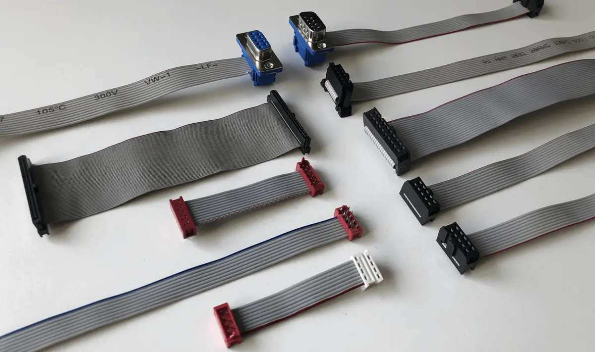
Specify the IDC connector at each end and its permitted cable construction. Insulation-displacement contacts terminate compatible insulated conductors; not every flat cable suits an IDC connector.
Identify each end separately when the build uses different connectors, crimp contacts or another termination. Provide the exact part references for project feasibility review.
Add routing instructions to either termination arrangement. Folds, split lengths and strain relief are installation details that can be combined with the chosen ends, rather than a separate connector type.
Check two interfaces: the connector must mate with the equipment, and its contacts must accept the selected cable. Connector contact pitch and cable conductor spacing are separate specifications. Neither position count nor the word “ribbon” confirms both.
Review the connector's permitted conductor construction, wire gauge and insulation dimensions, plus the specified termination method and strain relief. Electrical and temperature limits belong to the selected parts and operating conditions; there is no single rating for all ribbon assemblies.
This page concerns insulated-wire ribbon assemblies. Flexible flat cable (FFC) and flexible printed circuits (FPC) have different constructions and mating requirements. A similar width or pitch does not make them interchangeable with IDC ribbon cable.
If your drawing calls for FFC/FPC, identify it in the inquiry so the scope and feasibility can be reviewed separately.
Start with what you know. Mark open questions so we can clarify the selected cable, connectors and assembly details before arranging a build.
Add these views to your drawing or photos so both ends can be reviewed against the same connection definition.
Label the connectors A and B. State whether each view looks at the mating face or the wire-entry side. Use the exact connector drawing's cavity numbering; a view from the opposite side can mirror the apparent order.
Locate pin 1 from each selected connector's drawing and identify the corresponding cable conductor. A red edge stripe is a cable reference, not proof of pin 1, polarity or a straight-through connection.
Show the key or latch, cable-exit direction and any fold or strain relief. Turning a connector or folding the cable does not by itself define the electrical mapping: approve the physical arrangement and the pin table together.
The whole assembly and close-up views show the cable route, red edge stripe and connector entry. Pin numbering and electrical connections still need the selected connector drawings and an approved pin-to-pin table.
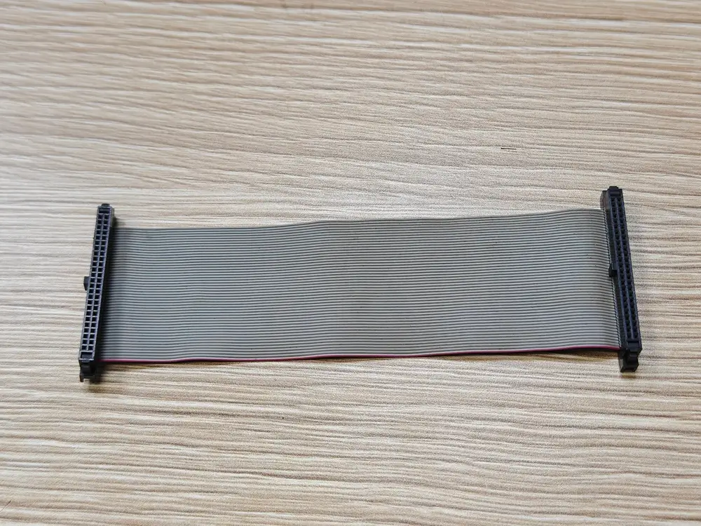
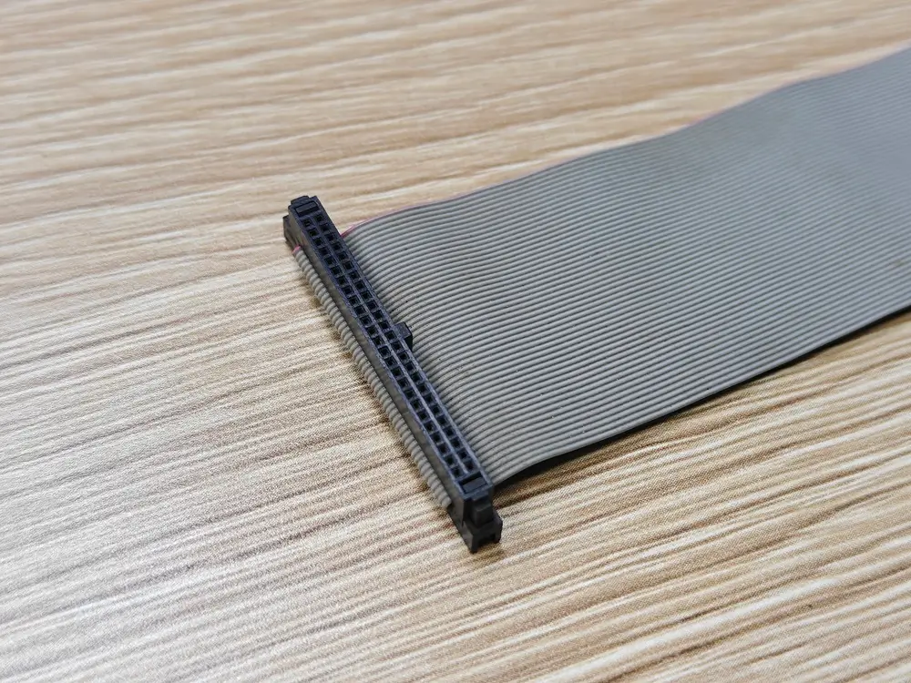
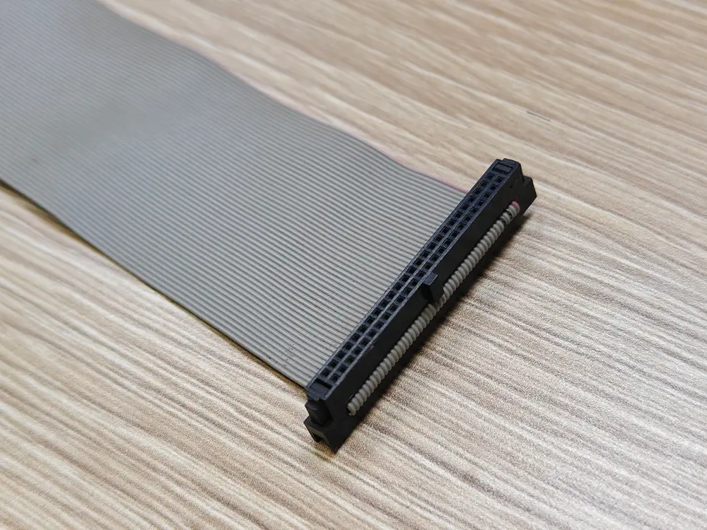
For the drawing conventions, see the cable pinout and polarity guide.
Choose the page that matches what you are buying; this avoids quoting the wrong scope.
Choose this page when connectors, pinout, pin-1 orientation, length or routing are part of the requirement.
Choose bulk cable when you need cable by reel or length without a completed terminated assembly.
Bulk flat ribbon cableWe use the stated assembly details to clarify the project and compare suitable supplier options.
Review connector, pitch, conductor count, pinout and orientation.
Confirm length, tolerance, fold, split and routing details that affect the finished assembly.
Match and compare suitable suppliers based on the confirmed scope.
Coordinate samples, revisions and production follow-up after the specification is confirmed.
The approved pin table and assembly drawing define the inspection target. Every assembly receives continuity and short-circuit testing; acceptance limits and any requested records are confirmed for the project.
Not necessarily. Specify cable conductor spacing and connector contact pitch separately. Check both against the selected cable and connector documentation; one value alone does not define a suitable assembly.
No. The exact cable construction must be checked against the selected terminal specification and its permitted cable range. Matching conductor count alone is insufficient.
Pin-1 and connector orientation affect the finished terminated assembly. Providing them in the drawing, photo or written instruction reduces ambiguity before sampling.
Yes. Send clear photos of both ends, viewing direction, required length and quantity. We can start the review and clarify any unresolved pin mapping before arranging the build.
Every cable assembly receives continuity and short-circuit testing. Pull-force testing is sampled and defined for the project.
Yes. If you need cable by reel or length without terminations, use the bulk flat ribbon cable page so the request is scoped correctly.
Include both connector references, cable construction, a pin-to-pin table, labeled end views, finished length and quantity. If a detail is unknown, mark it for review rather than guessing.