
TRADING & SOURCING PARTNER
Custom JST Cable Assemblies
Source custom JST cable assemblies for equipment builds, sample approval and repeat orders. Zeakka coordinates connector sourcing and assembly review around your drawing, BOM or sample details.
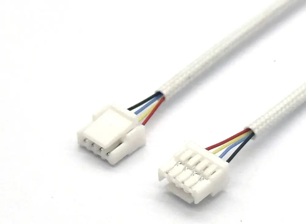
PH-to-PH, prepared wire ends, PH-to-USB and compatible extension configurations, with project-specific wiring.
Need a finished lead or harness rather than loose components? Define both ends, housing positions, length and pin-to-pin wiring for a custom XH cable quote.
1.25 mm secure-lock cable leads with custom lengths, pinouts and wire protection.
3.96 mm cable leads and harnesses with project-specific ends, wiring, lengths and protection.
Source custom SH leads, SH-to-SH cables and mixed-series assemblies. Define both ends, wire, pinout and length with Zeakka, your sourcing and supply partner.
Choose the JST interface before specifying the cable
Start with the connector already installed in your equipment, then define how the completed cable must connect and route. A series name or pitch alone does not establish a mating pair.
Match the equipment interface
Use the exact board header or mating housing reference. When identification starts from a sample, record the mating face, latch and markings before choosing a cable-side connector.
Choose the connection layout
Define single-ended leads, connections at both ends or a branched harness. Identify any different connector or prepared wire ends separately; identical housings do not establish a straight-through pinout.
Check the installed route
Review available space, wire exit and handling needs. Define any sleeving or branch protection alongside the cable layout so the proposed assembly can be checked against the equipment.
If an off-the-shelf assembly already meets the approved interfaces, pinout, wire and length, it may suit the project. A custom request is useful when those details need to change. Use the off-the-shelf vs custom cable assembly guide to compare the requirements.
Agree the component sourcing route
Original JST connectors can be sourced for use within finished cable assemblies, subject to the exact references and availability. They are not supplied as standalone original connector sales. Unbranded compatible candidates follow a separate drawing and mating-interface review; a shared pitch does not establish interchangeability. See the JST alternative review guide.
For a two-circuit wire-to-wire lead, use the custom JST RCY cable assembly page to review the mating halves and polarity requirements.
A delivered project in detail
Delivered project
PH-to-PicoBlade mixed-interface cable
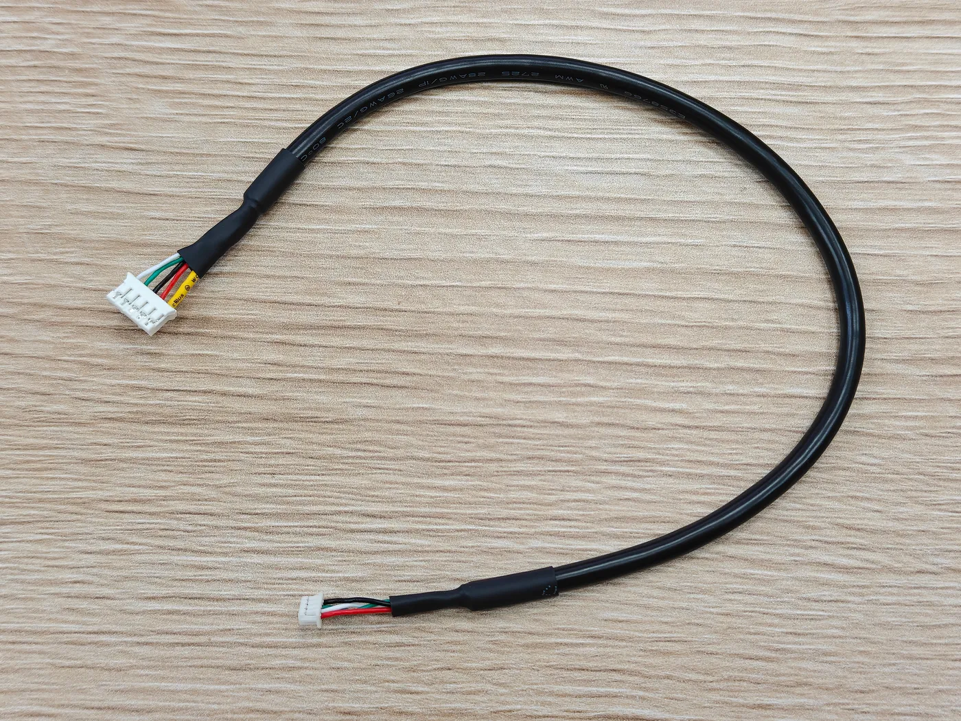
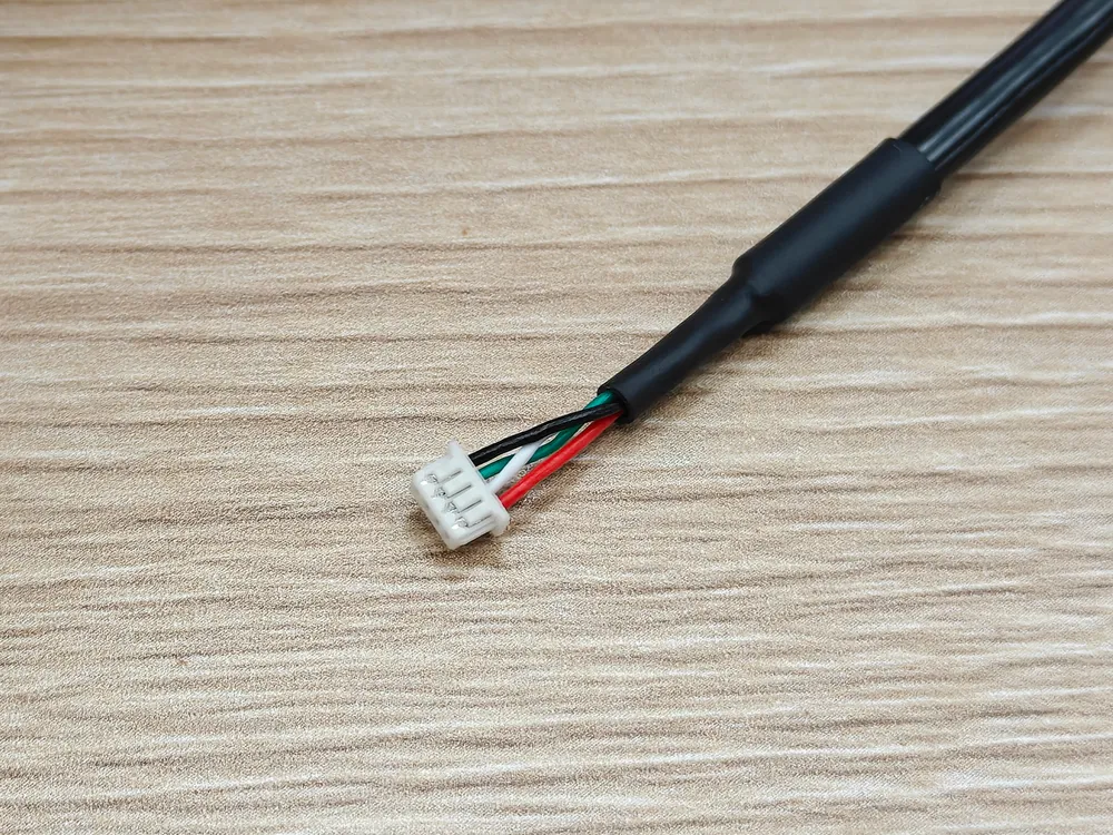
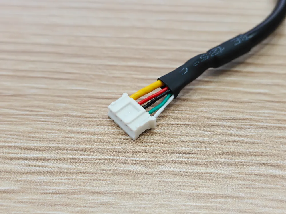
This delivered project combined a five-position PH-style housing and a four-position PicoBlade-style housing on a black jacketed cable, with heat-shrink sleeves at the cable exits.
- Drawing preparation
- Zeakka prepared the project drawing for the mixed-interface assembly, defining the connection list, cable construction and nominal dimensions.
- Sampling and testing
- Zeakka handled sample development and testing before bulk production. The photographs show the complete assembly and the construction at both cable exits.
- Bulk production and delivery
- Zeakka coordinated bulk production through completed delivery. For a similar request, provide the mating interfaces, connection list and required quantities.
View project drawing, connection list and BOM
Connection list from the project drawing
| Wire | A cavity | B cavity / destination | Signal |
|---|---|---|---|
| Yellow | 1 | Cable shield | Shield |
| Red | 2 | 1 | VCC |
| Black | 3 | 4 | GND |
| Green | 4 | 3 | D+ |
| White | 5 | 2 | D− |
A is the five-position PH-style end; B is the four-position PicoBlade-style end. The shield lead has no assigned B cavity. Cavity numbers follow the project drawing; confirm the connector viewing direction for any new build.
BOM excerpt
Component references and cable construction from the supplied project drawing. A reference followed by “or compatible” does not establish original-brand parts. This excerpt is not a certification or an inspection report.
- 1. Jacketed cable
- 2 × 24–26 AWG power conductors + 2 × 28 AWG twisted data conductors; foil/copper-braid shield; black PVC jacket, 5 mm maximum outside diameter
- Qty 1
- 2. End B housing
- PicoBlade 51021-0400 reference or compatible; 4 positions, 1.25 mm pitch
- Qty 1
- 3. End A housing
- PHR-5 reference or compatible; 5 positions, 2 mm pitch
- Qty 1
For a separate example of drawing-led sourcing and sample coordination, read the Belgian JST-compatible cable assembly case study. This is a separate case; the photographs above do not identify that customer's order.
What to send for a JST cable assembly quote
Attach the information you already have and identify open questions. A complete drawing is helpful, but you can begin with a BOM, sample details or photographs.
- Interfaces and component choice
- JST housing/contact references, mating parts and any different connector at the other end. State original-component requirements or permission to evaluate alternatives.
- Circuit map
- Cavity-to-cavity connections, numbering and viewing direction, polarity and any unpopulated positions.
- Wire and installation
- Wire specification and gauge, electrical duty, routing environment, and any jacket, sleeve or other protection requirements.
- Dimensions
- Finished length, measurement datums and tolerances; branch lengths and prepared-end dimensions where applicable.
- Quantity and schedule
- Sample, first-order and expected repeat quantities, packaging needs and target date.
- Approval and documents
- Drawing/BOM revision, sample acceptance points, required inspections and project-specific compliance documents.
From project review to production approval
Zeakka is a trading and sourcing partner. We coordinate supplier selection, quotation, sample review and production follow-up around the agreed specification.
1. Review feasibility and quote scope
Resolve missing specifications, compare suitable supplier options and identify proposed deviations. Confirm the component route, quantity, price and timing in the quotation.
2. Approve the sample and revision
Agree the drawing and BOM revision. Review the sample against the mating interface, circuit map, dimensions and equipment installation; record changes before production approval.
3. Confirm production checks
Each cable assembly receives continuity and short-circuit testing. Pull-force testing is sampled and project-specific. Agree any additional inspection, documentation and packaging requirements for the order.
JST cable assembly FAQ
Can I start without a complete JST cable drawing?
Yes. Send the available BOM, mating-part references, sample details or clear photographs, and mark what is unknown. These support identification and feasibility review; the build specification still needs to be agreed before production.
Can I discuss samples before a repeat order?
Yes. Provide the sample quantity, intended first order and expected repeat requirement separately. Sample arrangements and production quantities are reviewed for the specific configuration; an expected repeat order is not a confirmed minimum order.
When are MOQ, price and lead time confirmed?
They are confirmed in the quotation after the configuration, component availability, quantities and approval requirements have been reviewed. Include your target date so any sourcing or sample constraints can be identified.
Request a project quote
Send your drawing, BOM, reference, quantity and application so we can clarify the requirement before quoting.