
JST GH vs SH: Choosing a Compact Connector for a Custom Cable Assembly
Table of Contents
JST GH and SH are compact wire-to-board systems with different pitches, mating parts and wire requirements. GH uses a 1.25 mm pitch and an external positive latch. SH uses a 1.00 mm pitch and a different housing and header interface. They do not mate with each other.
Quick choice: keep the matching series when a board header is already fixed. For a new design, review GH when a positive latch and its wire range suit the assembly; review SH when finer contact spacing and its smaller-wire range suit the layout. Compare the complete mated connection, including access and wire routing, before releasing either design.
GH vs SH at a glance
The following are original JST catalog references, checked on 29 September 2026. They do not rate a complete cable assembly or an unbranded alternative.
| Item | JST GH | JST SH |
|---|---|---|
| Contact pitch | 1.25 mm | 1.00 mm |
| Mating arrangement | External positive latch | Different housing/header retention geometry; no GH-style external release latch |
| Contact example | SSHL-002T-P0.2 | SSH-003T-P0.2-H |
| Contact conductor range | AWG 30–26 | AWG 32–28 |
| Contact insulation outside diameter | 0.76–1.00 mm | 0.40–0.80 mm |
| Catalog current rating | 1 A AC/DC with AWG 26 | 1 A AC/DC with AWG 28 |
| Catalog voltage rating | 50 V AC/DC | 50 V AC/DC |
| Catalog temperature range | −40 to +105 °C | −25 to +85 °C |
| Four-position housing example | GHR-04V-S | SHR-04V-S or SHR-04V-S-B; different housing variants |
| Board-side styles shown | SMT top and side entry | SMT top and side entry; check availability for the selected circuit count |
Temperature ranges include current-induced temperature rise. Confirm the complete ordering reference, drawing revision and mating parts. Sources: JST GH catalog, pages 1–3; JST SH catalog, pages 1–4.
The equal current figures have different wire conditions. They do not mean any GH or SH harness can carry 1 A under any installation conditions. Review the chosen wire, loaded circuits, ambient temperature and duty cycle as one assembly.
Browse GH-series alternative connectors, SH-series alternative connectors. These product pages cover alternatives; select the exact housing, contact and mating interface for your application.
Identify GH and SH without relying on a seller's label
An existing board header is the starting point. Obtain its complete part number from the drawing or bill of materials, then identify the intended cable-side housing and contact. A listing labeled only “mini JST” does not establish a mating system.
When only samples are available, record the circuit count and photograph the mating face, wire-entry side, retention features and board header. Measure contact-center spacing rather than plastic body width. On a four-position part, the first-to-last centers span three pitches: 3.75 mm for GH and 3.00 mm for SH. Treat that measurement as a screening aid and confirm the drawing before ordering.
Distinguish two retention functions. GH's external latch holds the mating connector pair together. SH's housing lance retains the individual terminal inside the cable housing; it is not an equivalent external release latch. Terminal seating and connector mating therefore need separate inspection checks.
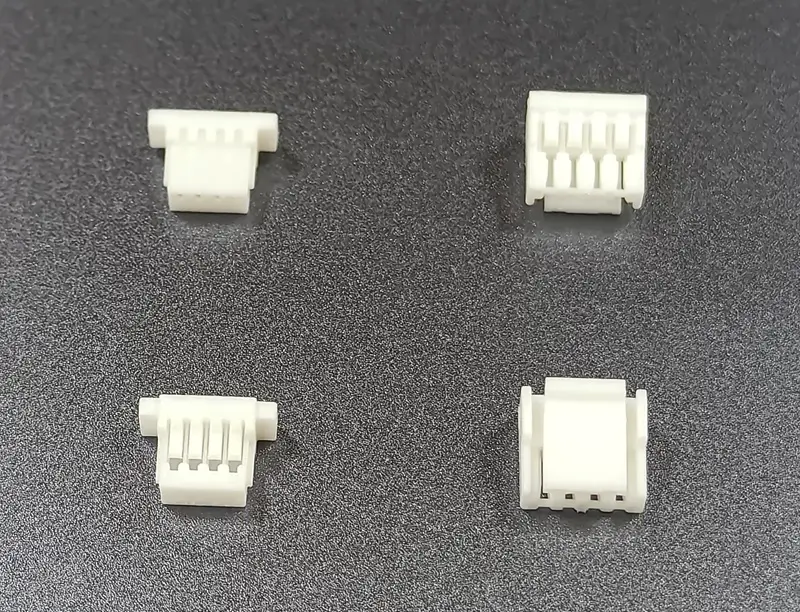
Alternative housings for the GH and SH series. Shown for visual comparison; original JST catalog specifications do not rate these samples.
Decide around the board, the wire and the enclosure
The board interface is already fixed
Specify the approved mating parts. A smaller SH housing cannot replace a GH housing on the same header, and changing only the cable end does not solve the mismatch. A change of series requires review of the PCB header and footprint, harness components, pin mapping and mechanical clearance.
If two boards intentionally use different interfaces, a GH-to-SH assembly can connect them through correctly matched ends. Define the mapping from each end's pin-one reference; neither equal circuit count nor matching wire colors proves the intended electrical connection.
Board space is tight
SH's finer pitch reduces the distance occupied by a row of contact centers. It does not, by itself, settle the overall fit. Compare the selected header and housing drawings in the intended orientation, then include insertion travel, wire bend space, nearby components and the enclosure cover.
Choose top or side entry around the actual route out of the connector. The room needed to insert or remove the plug can matter as much as the footprint. A compact prototype that can be assembled only before the cover is installed may need a different service sequence.
The wire specification is already fixed
Check conductor size and insulation outside diameter independently. For example, AWG 28 falls within both listed contact ranges, but a 0.60 mm insulation diameter falls below the stated GH range, while a 0.90 mm diameter exceeds the stated SH range. Matching the AWG alone is insufficient.
Keep the approved cable specification in the RFQ. If it does not fit the terminal, review the wire or connector selection with the design owner. Do not thin the insulation or change conductor strands simply to make the terminal accept an unsuitable wire.
The product needs access for disconnection
For GH, leave access to operate the external latch. For either series, plan a way to disconnect the housing without using the wires as a handle. Keep harness support and strain relief separate from the connector selection.
A latch is not a vibration qualification. If movement, shock or repeated maintenance matters, specify the test conditions and acceptance criteria for the actual assembly instead of choosing from the latch appearance alone.
Contacts and assembly details that belong on the drawing
The contact references in the table are different components. Do not substitute a similarly named terminal or treat GH and SH contacts as interchangeable. Record the exact terminal, wire specification and selected housing variant in the harness bill of materials.
Specify the pin numbering as seen from a stated view, such as the mating face. Include empty positions, wire colors and any intentional crossings. This makes the inspection drawing usable even when the two ends have different orientations or connector series.
Agree the crimp inspection requirements for the selected contact and wire combination, including conductor capture, insulation support and terminal seating. Ask for the applicable dimensional and pull-test criteria rather than accepting a generic close-up as proof of process quality. Continuity and short-circuit checks should use the approved pin map.
What to send for a custom GH or SH cable quote
Provide the information that fixes the mating interface first, then the assembly requirements:
- Mating parts: housing and board-header references, circuit count, contact reference and required manufacturer or alternative-part approval route.
- Wiring: a labeled pin-to-pin drawing, conductor and insulation specifications, wire colors and any intentionally unused positions.
- Dimensions: finished length, tolerance, measurement endpoints and routing restrictions.
- Configuration: requested end terminations or branches, followed separately by protection, identification and packaging requirements for project review.
- Acceptance and quantity: sample and production quantities, operating conditions, continuity checks and any specified mechanical or environmental tests.
For a finished cable assembly, Zeakka can source original JST components for the project, subject to exact part selection and availability, or review unbranded alternatives. Original components are not sold separately. An alternative needs its own drawing, mating and application review; original JST ratings do not automatically apply to it. The exact SH cable assembly configuration and any requested original-part availability are reviewed for each project.
Explore custom JST GH cable assemblies, consult the GH cable sourcing guide, or send your GH or SH drawing for an RFQ. If the sample is unidentified, include clear photographs and dimensions with the details you can confirm.
Frequently asked questions
Can JST GH and SH plug into each other?
No. They have different contact spacing and mating geometry. Use the intended housing, terminal and header combination. An assembly with GH at one end and SH at the other is a cable between two interfaces, not a directly interchangeable connector pair.
Is SH always the better choice for a small product?
No. Compare the complete installed envelope, wire route and assembly access. SH has finer contact spacing, while the wire specification, mating arrangement or service method may make another interface more suitable.
Can the same AWG 28 wire be used with both?
Possibly, but only after checking the exact insulation diameter and the approved contact and crimp specification. A shared conductor gauge does not establish that both insulation-support sections fit the wire.
Does the GH latch make a harness vibration-proof?
No. Define the vibration profile, mounting, cable support and electrical acceptance criteria, then obtain evidence for the selected assembly. Connector retention is one part of that assessment.
Are SH and SR the same connector?
They are different termination systems. JST identifies compatibility between SH headers and SR IDC sockets; that does not make GH compatible with SH, or make SH crimp contacts and SR terminations interchangeable. Confirm the complete mating pair and wire requirements for the selected system. See the SH catalog, page 3.
What if I have a sample but no part number?
Send mating-face, side and wire-entry photographs, the board-header view, circuit count and measured contact spacing. Include any equipment drawing or label available. Resolve the interface and pin mapping before approving a production sample.
Share this article
Help others discover this content