
Female Header Compatibility: Pin Size, Insertion Depth and Housing Clearance
Table of Contents
Two connector strips can share a pitch and position count yet form an unsuitable contact pair. The pin may have the wrong cross-section, stop before adequate insertion or interfere with the socket housing. A hand fit alone does not establish the electrical or mechanical suitability of that interface.
Review the female contact's intended mating pin before calculating the complete board arrangement. Keep the pin shape, dimensions and tolerances, insertion limits and housing clearance together in one interface record. The board stack-height guide then addresses how an approved interface sits between two PCBs.
Match pin geometry and define insertion from the socket entry face
Conceptual cross-sections and insertion datum, not a manufacturer drawing. Equal nominal width and diameter do not establish square-to-round interchangeability. Insertion is not contact wipe.
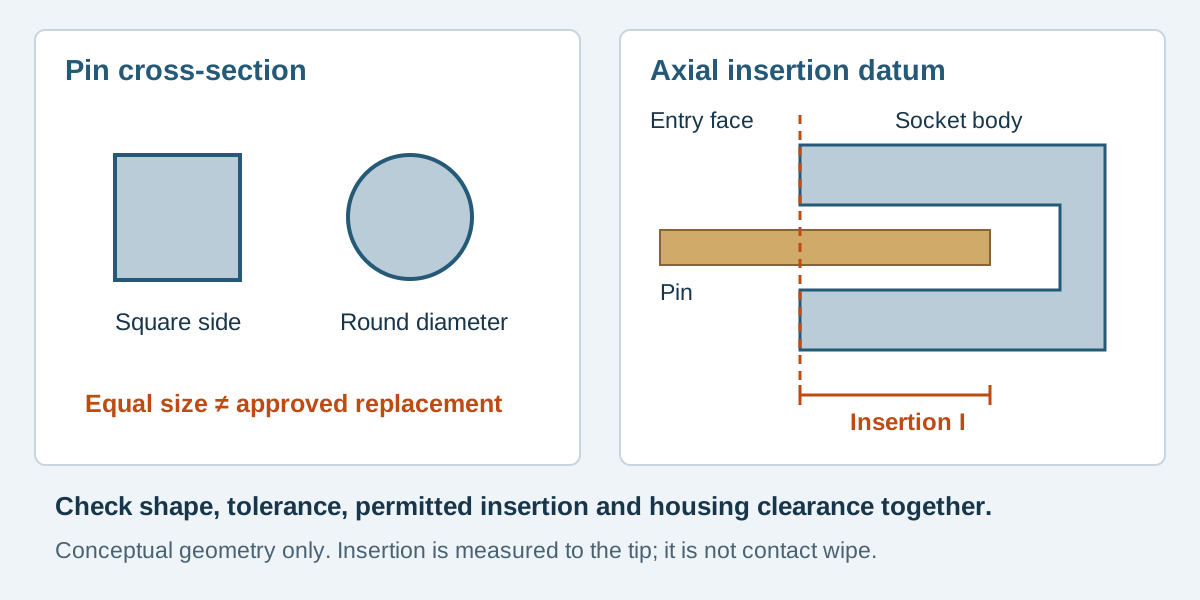
Conceptual illustration. Fictional examples are not approved product configurations, tooling instructions or inspection results.
Pitch locates contacts; pin size defines a different interface
Pitch is the centre-to-centre spacing between adjacent positions. The pin cross-section describes the metal entering an individual contact. Those dimensions answer different questions, even when catalog descriptions place them next to each other.
For a square pin, preserve the specified side dimension and tolerance. For a round pin, preserve its diameter and tolerance. Do not treat an equal nominal width and diameter as interchangeable: their contact geometry differs. Likewise, the diagonal of a square pin is not a socket's allowable round-pin diameter.
The lead-in, tip shape, straightness and allowed misalignment can affect entry. Use the selected manufacturer's interface information; do not force a trial part into the socket to establish an undocumented size range. A visibly enlarged contact opening after a trial is not evidence of compatibility.
Scroll sideways to read all columns.
| Interface field | What the reviewer needs | What does not replace it |
|---|---|---|
| Position layout | Pitch, row spacing and cavity count | Total body length |
| Mating pin | Shape, cross-section and controlled tolerance | Pitch alone |
| Socket applicability | Approved mating geometry or identified mate | Similar-looking housing |
| Insertion | Defined entry datum and permitted travel | Exposed pin length alone |
| Surrounding geometry | Body clearance, stops and alignment features | A continuity beep |
| Surface system | Specified finish and applicable mating evidence | Color of the contact surface |
Read a documented socket and header example
Samtec SSW-105-01-G-S identifies a five-position, single-row socket strip on 2.54 mm pitch. TSW-105-07-G-S identifies a five-position, single-row header in the TSW square-post family. The SSW through-hole catalog lists TSW among its mating series, identifies the socket as a .025-inch square-post type and gives an insertion-depth range of 3.68–6.35 mm.
Those documents establish a useful starting point for an interface review. They do not approve every variant or installation using the series names. Preserve the complete orderable references, obtain the applicable controlled prints and check the chosen post length, tolerances and surrounding geometry. Samtec also directs users to confirm configuration against the series print before final design-in.
The .025-inch post designation corresponds to 0.635 mm arithmetically and is commonly presented as 0.64 mm in metric catalog text. Rounded catalog presentation is not a new manufacturing tolerance. Keep the controlling units and tolerances from the drawing instead of comparing rounded numbers as exact limits.
Define insertion from the socket entry face
For this discussion, insertion I is the axial distance from the socket's defined entry face to the pin tip in the intended assembled state. Mark that face on a section view. The length of pin exposed above its own insulator is a different dimension.
Insertion also differs from contact wipe and the length of metal touching the spring. Those depend on the internal contact design. A generic cutaway can explain the quantities but cannot locate the actual contact zone inside an unidentified socket.
Check the least insertion and greatest insertion produced by the controlled assembly geometry. At the low extreme, compare with the applicable engagement requirement. At the high extreme, check both permitted insertion and physical obstructions. A socket catalog's maximum depth is not permission for the pin's own housing to collide with the socket before reaching that depth.
A fictional two-candidate interface review
EX-FH-38 compares two proposed pin interfaces for a specified socket. Both candidates use the required 2.54 mm pitch and five positions. The project has not yet approved a substitute connector. The insertion values below are assumed installation results for this exercise, not tolerances assigned to the Samtec example.
Scroll sideways to read all columns.
| Review field | Candidate A | Candidate B |
|---|---|---|
| Pin cross-section | Documented .025-inch square type | 0.64 mm round pin |
| Resulting insertion | 4.20–4.50 mm | 4.20–4.50 mm |
| Evidence for socket acceptance | Square-pin family documentation available; exact print review remains | No applicable round-pin acceptance provided |
| Housing clearance | Still requires drawing review | Still requires drawing review |
| Decision | Continue exact-part review | Hold pending compatible-interface evidence |
Using the cited 3.68–6.35 mm insertion range as a reference, both assumed insertion intervals sit within it numerically. Candidate B still lacks evidence that its round pin belongs in that socket. Candidate A is not released either: the full reference, tolerances, finish and interference checks remain necessary. One favourable dimension cannot close the entire interface review.
Verify alignment and the housing stop separately
A pair may be suitable when aligned yet vulnerable to an assembly that drives the pins sideways. Define how the equipment locates the two halves, how the operator approaches them and which feature stops further travel. The permitted alignment and mating method must come from the selected parts and installation design.
Do not use socket contacts as an improvised alignment tool for a misplaced board. Where mechanical supports establish position, include their locating datums in the review. Check neighbouring plastic, polarization features and component keep-out space through the full insertion motion, not only at the final position.
For sourcing, provide both references even if only one half is being purchased. Mark whether the other half is a fixed customer interface or merely a candidate. A supplier cannot assess a proposed female header against “standard male pins” when the pin shape, post length and housing envelope remain undefined.
Female header questions
Does matching 2.54 mm pitch mean two parts mate?
No. Pitch is one layout dimension. The pin geometry, contact applicability, insertion, plating and surrounding parts still need review.
Can a round pin replace a square pin of the same nominal size?
Only with applicable evidence for that socket and the proposed round pin. Equal nominal dimensions do not establish the same contact interface.
Is deeper insertion always better?
No. Stay within the manufacturer's applicable limits and the permitted physical geometry. Excess travel can create interference or damage rather than useful engagement.
Send both sides of the interface for review
For female headers, provide the socket specification, exact mating pin drawing, desired insertion interval and housing section. Include fixed equipment constraints and expected quantities. Contact Zeakka to coordinate review of a proposed supply option. The original Samtec references are technical examples, not an offer of loose original parts or proof that an alternative inherits their specifications.
Share this article
Help others discover this content