
JST Adapter Cables: Specifying Different Connectors at Each End
Table of Contents
A JST adapter cable connects two different physical interfaces through a defined wiring arrangement. It may help connect an existing board to a different module without changing either board. However, a connector that fits at each end does not establish electrical compatibility. The equipment documentation must confirm what each circuit does and whether the two devices can operate together.
For a passive adapter, the essential decisions are the mating parts at both ends, the function-to-function connections and the requirements along the entire cable path. A passive cable does not convert supply voltage, logic levels or communication protocols.
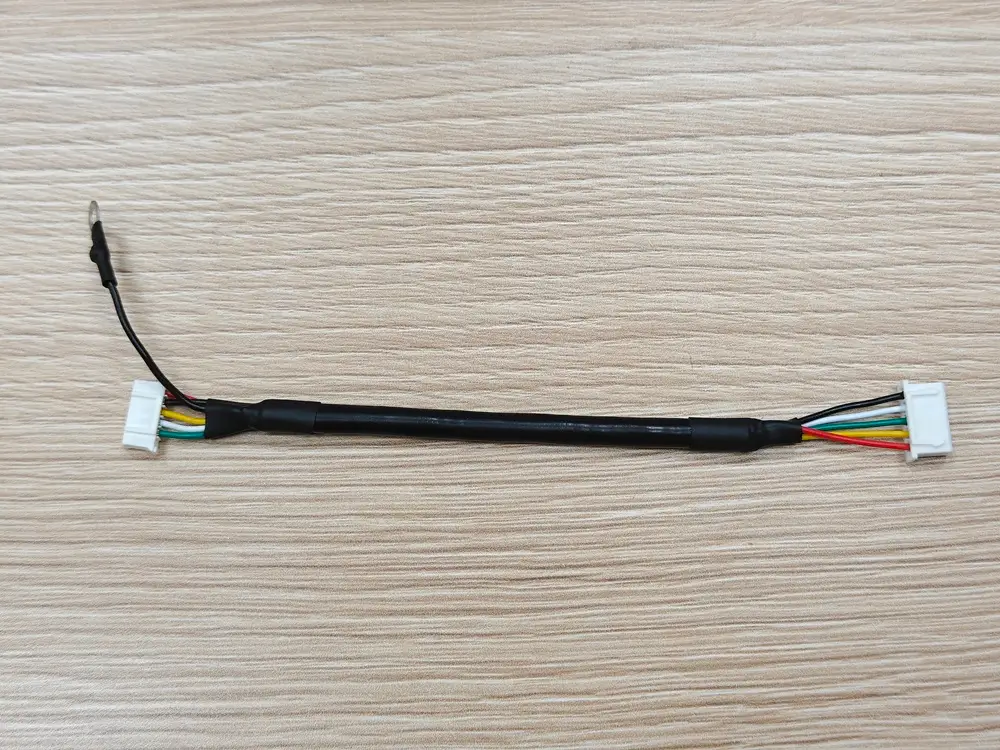
XH-to-PH cable assembly using alternative connector housings. The visible ring-terminal lead is an additional feature; its electrical purpose is not defined by this photograph.
Define two interfaces, not one cable label
“JST adapter” is a starting description, not a build specification. Identify the exact mating connector on Device A and separately on Device B. For each end, record its manufacturer and part number, circuit count, keying, orientation and drawing revision. Then specify the cable-side housing and contacts that mate with that interface.
A family name or pitch alone is insufficient. For example, JST lists GH at 1.25 mm pitch and PH at 2.0 mm pitch, with separate housing, contact and header systems. A cable joining those interfaces needs the appropriate termination at each end; the two housings do not mate directly to each other. See the JST GH catalog, pages 1–3, and JST PH catalog, pages 1–3.
Use the common JST connector types guide to narrow identification. Once identified, GH-series alternative connectors, PH-series alternative connectors and XH-series alternative connectors provide relevant component options for review. These options still require approval against the actual mating parts.
The photographed example uses a five-position XH-series alternative housing and a six-position PH-series alternative housing with one empty cavity. These identities were confirmed for the sample; they do not establish its pin map. The additional ring-terminal lead also requires its own definition on the assembly drawing rather than an assumed ground or branch connection.
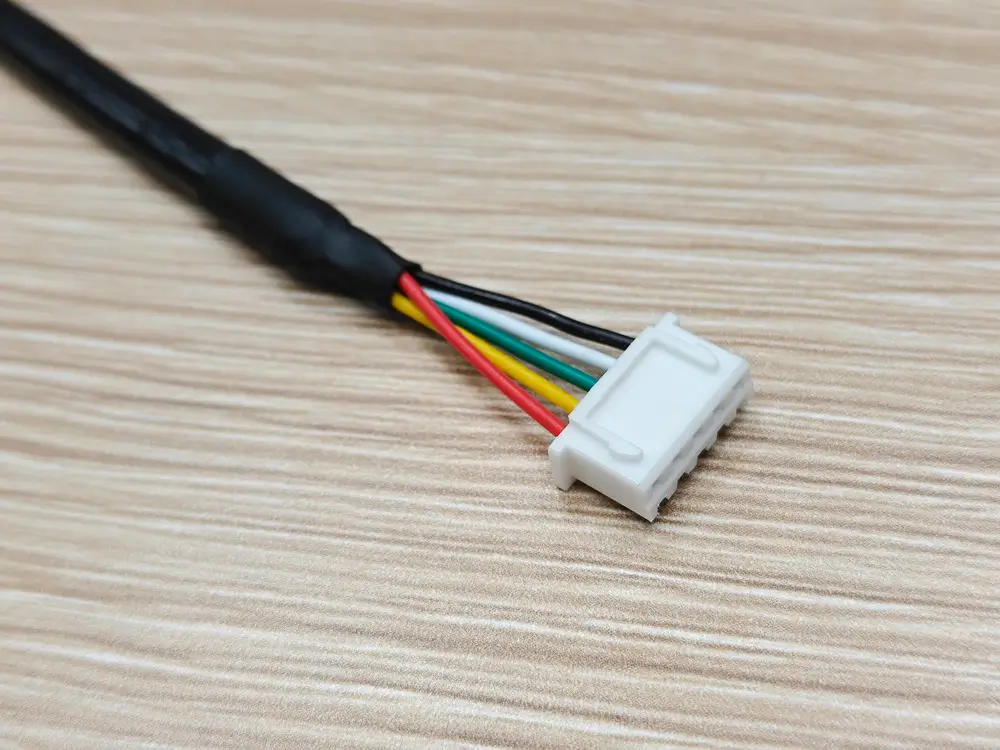
XH end: five-position alternative housing. The photograph identifies the physical end, not its circuit assignments.
Match circuit functions before choosing the wiring pattern
Obtain the interface definitions for both devices. Check supply polarity and voltage, signal direction, logic levels, return paths and any required shielding. For a communication connection, confirm the supported protocol and applicable cable constraints. Equal circuit counts do not imply matching assignments.
Define every connection by its endpoint positions and circuit function. Do not assume that position 1 is power, that matching colors carry matching signals, or that “straight-through” describes the intended result unambiguously. Pin 1 and the viewing direction must follow the drawings for the specified parts. A mating-face view and a wire-entry view can otherwise produce an apparently reversed map.
An illustrative review might identify a supply, its return and a control signal at each device. Connect the corresponding functions only after confirming their electrical compatibility; the position numbers may differ between ends. This is an illustration of the review process, not an official JST pin assignment or a wiring instruction for a particular device.
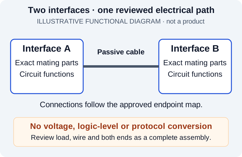
Illustrative design diagram, not an available product or a connector drawing. Each interface and the complete wiring path require their own review.
Review the complete electrical and mechanical path
The larger connector does not set the rating of the finished adapter. Review both mating pairs, contacts, wire sections and any intermediate joints for the required operating voltage, continuous and peak current, duty cycle and environment. Include voltage drop along the selected cable length and the installation's temperature conditions. A catalog component rating is not automatically a finished-assembly rating.
Wire selection must work with both terminations. As one specific catalog example, JST's GH contact SSHL-002T-P0.2 accepts AWG 30–26 with insulation outside diameter of 0.76–1.0 mm. The PH contact SPH-002T-P0.5S lists AWG 30–24 and 0.8–1.5 mm. These are original JST component data, not ratings for an unbranded alternative. See page 2 of each GH and PH catalog.
An overlapping conductor range is only an initial screening result. Confirm insulation diameter, wire construction, the specified contacts and the crimp process as well. Do not assume that the wire used at one end can be terminated at the other.
If the application requires different wire sizes at the two ends, a transition needs separate engineering review. Its termination method, insulation, strain relief and space requirements must be defined and validated. A change in wire size does not increase the capacity of a smaller contact or wire section. Feasibility depends on the proposed construction; it is not a promise that every pair of connector families can be combined.
Also check installed cable length, bend space, wire exits, latch access and support near each end. An adapter that fits on a bench may load a connector or interfere with a cover inside the equipment.
Specify unused positions explicitly
Different circuit counts are possible only when the equipment requirements allow them. For every unused position, state whether it is an empty cavity, a fitted contact without a conductor, or another specifically approved arrangement. A disconnected conductor must have a defined, insulated termination if included.
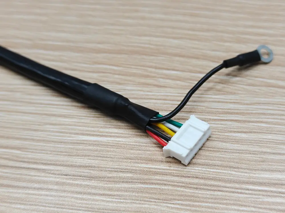
PH end: six-position alternative housing with one empty cavity. Its cavity number and the ring terminal's function must be specified in the project drawing.
Do not join spare positions together, connect them to ground or omit a required return simply to reconcile the counts. If a device requires an identification resistor, jumper or other circuit element, that requirement belongs in the design and changes the assembly specification. Leaving a position blank is not a substitute for understanding its purpose.
Turn the reviewed design into an orderable assembly
Submit both interface references, the approved connection map, load information, cable length and routing constraints together. Ask for review of the complete construction rather than a generic “PH-to-GH” or “JST-to-JST” cable. Define acceptance checks against that design, including intended continuity, absence of unintended connections and the required mechanical fit. Continuity alone does not verify that the devices are electrically compatible.
Zeakka sells alternative connectors. For finished cable assemblies, original JST components may be sourced subject to specific part-number availability, or unbranded alternatives may be evaluated for the application. Original JST connectors are not sold separately by Zeakka. SH and ZH cable configurations require project review; an adapter request does not imply stock availability or approval of every series combination.
Review custom JST PH cable assemblies, custom JST GH cable assemblies or custom JST XH cable assemblies for the relevant end, then send both interface requirements for adapter review. Identify which details are confirmed and which still require review so the proposed assembly can be evaluated before ordering.
Share this article
Help others discover this content