
Common JST Connector Types Compared: SH, GH, ZH, PH, XH and VH
Table of Contents
“JST connector” is not a complete part specification. This guide compares six wire-to-board crimp systems—SH, GH, ZH, PH, XH and VH—to help you identify an existing interface or shortlist a connection for a new cable assembly. It does not cover every JST series.
For an existing product, start with its board-side header. For a new design, start with wire, load, available space and assembly requirements. Pitch is a useful first filter; the correct housing, contact and header must still be identified together.
Identify an unknown connector in five steps
- Find a reference first. Check the equipment drawing, PCB bill of materials, packaging or supplier record for the complete header and housing numbers. Record suffixes rather than shortening the number to a series name.
- Count positions and record occupied positions separately. A six-position housing with four wires is still a six-position interface. Photograph the mating face so empty cavities and orientation are clear.
- Measure contact-center spacing. On a uniformly spaced, single-row connector, measure the first-to-last contact-center distance and divide by the number of intervals. Four positions have three intervals. Do not divide housing width by the number of pins.
- Compare the shape and mating features. Check the cavity profile, keying, retention features, wire exit and the corresponding header. Take a straight-on mating-face photo and a side view. Housing color alone is not a reliable identifier.
- Match the drawing before ordering. Confirm the complete mating pair and terminal, then verify pin numbering and polarity. If the dimensions or shape disagree, leave the identity unconfirmed instead of forcing the nearest-looking part to fit.
For four equally spaced positions, a 6.00 mm first-to-last center measurement suggests 2.00 mm pitch; 7.50 mm suggests 2.50 mm pitch. Those measurements help distinguish candidates. They do not prove that a connector is an original JST product or establish its complete part number.
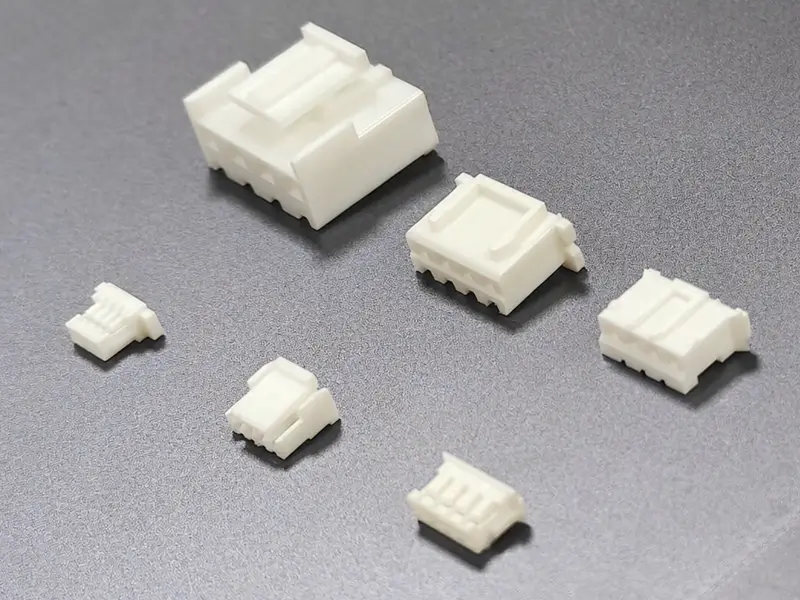
Alternative housings identified as SH, GH, ZH, PH, XH and VH. Photographs are not dimensional drawings; original JST catalog specifications do not rate these samples.
Browse SH-series alternative connectors, GH-series alternative connectors, ZH-series alternative connectors, PH-series alternative connectors, XH-series alternative connectors, VH-series alternative connectors. These product pages cover alternatives; select the exact housing, contact and mating interface for your application.
Six series at a glance
The electrical values below are original JST catalog references checked on 29 September 2026. Each current value retains its stated wire condition. They are not universal limits for all terminals, alternative parts or completed cable assemblies.
| Series | Contact pitch | Catalog current reference, AC/DC | Useful feature to check |
|---|---|---|---|
| SH | 1.00 mm | 1 A with AWG 28 | Compact interface; distinguish contact retention inside the housing from mating retention |
| GH | 1.25 mm | 1 A with AWG 26 | External positive latch and its release access |
| ZH | 1.50 mm | 1 A with AWG 26 | Housing profile and the exact board-header style |
| PH | 2.00 mm | 2 A with AWG 24 | Shrouded header and the selected through-hole or SMT footprint |
| XH | 2.50 mm | 3 A with AWG 22 | Shrouded header; nominal pitch is 2.50 mm, not 2.54 mm |
| VH | 3.96 mm | 10 A with AWG 16 and standard header; 7 A with AWG 18 and shrouded header | Outer locking feature and the specified header variant |
Sources: JST catalogs for SH, GH, ZH, PH, XH and VH, specification pages and associated housing/header drawings.
Use the current column to identify which catalog deserves closer review, not to approve a load. The final choice must account for the selected contact and wire, ambient conditions, populated circuits, duty cycle and temperature rise. A larger pitch alone does not qualify a harness for more current.
Look beyond pitch: retention, mounting and routing
Separate terminal retention from connector locking
A feature that keeps a metal terminal seated inside a plastic housing performs a different job from a latch that keeps the housing mated to its header. This distinction matters when reading terms such as “housing lance.” GH and VH have external locking features; the exact mating and release geometry still depends on the selected parts. Do not turn the presence of a latch into a vibration rating. Review cable support, release access and application testing separately.
Check the board-side option
The cited SH and GH catalogs show SMT top- and side-entry headers. ZH and PH include through-hole and SMT options, while the cited XH and VH drawings show through-hole options. Availability varies with the exact style and circuit count; these categories do not mean that every size is available in every arrangement.
Top versus side entry changes where the cable approaches the board. Through-hole versus SMT changes the board attachment and footprint. Neither choice can be inferred from a photograph of the cable housing alone. Use the selected header drawing to check the PCB layout and assembled envelope.
Reserve space for the complete connection
Allow for mating travel, latch access, cable bend radius and strain relief as well as the plastic body. A fine-pitch housing that fits between other components may still leave insufficient room to insert or remove the cable safely.
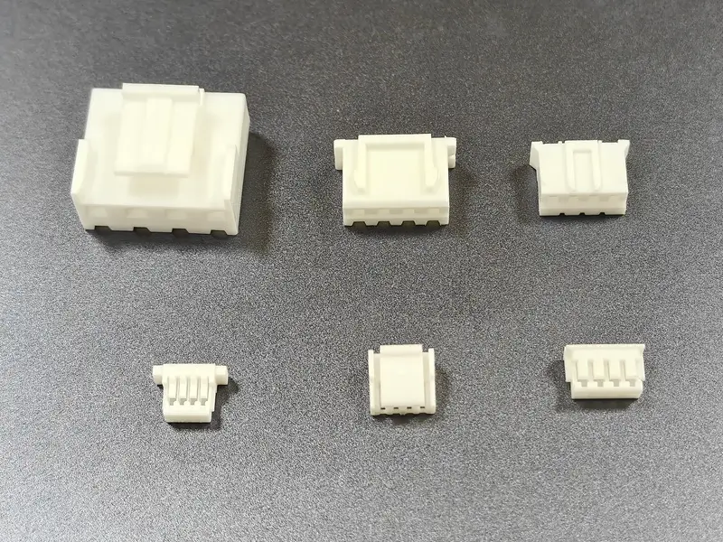
Another view of the same six alternative housing samples.
Narrow the shortlist around the actual constraint
| Your starting point | Next useful decision |
|---|---|
| An existing PCB or replacement cable | Identify and retain the approved mating interface; do not choose a different series just because it is easier to buy |
| Very limited board space | Compare the full SH, GH and ZH assembly drawings against wire requirements, routing and service access |
| A choice between PH, XH and SH | Compare their different pitch, terminal/wire combinations and header arrangements; decide which fits the application rather than treating them as interchangeable sizes |
| A load that exceeds the shortlisted interface's validated capability | Review a suitably rated system, including the exact VH variant where relevant, and check the entire electrical path |
| A cable that needs frequent access | Check the handling and release method in the installed position, and agree the required mating-cycle performance |
| An uncertain seller description | Request manufacturer references, dimensional drawings and samples before approving compatibility |
For a closer look at the two larger members of the PH/XH/SH comparison, read JST PH vs XH. SH uses a separate 1.00 mm interface; it is not a smaller housing that can be fitted onto PH or XH contacts. A change of series requires review of the header, terminals, footprint and assembly process as well as the housing.
Series names and part numbers are different levels of detail
“VH vs VHR” and “ZH vs ZHR” can look like comparisons between competing series. In the cited catalogs, VHR-4N is a VH housing reference and ZHR-4 is a ZH housing reference. The extra letters are part of component identification, not evidence of a separate connector family. See the VH housing table, page 2 and ZH housing table, page 3.
Similarly, a complete harness needs more than “four-pin JST.” Its specification should identify the cable-side housing, contact, board-side mating reference, wire and pin mapping. Confirm full ordering suffixes with the current drawing; a shortened reference can omit a meaningful variant.
Turn identification into a useful cable assembly RFQ
Prepare a small, complete identification package:
- Housing and mating header references, or clear photographs and measured dimensions where identification is unresolved.
- Circuit count, occupied positions and a labeled pin-to-pin drawing showing the viewing direction.
- Conductor size, insulation material and outside diameter, wire colors and any specified terminal.
- Finished length, tolerance, branch arrangement and length-measurement points.
- Quantity, application conditions, inspection requirements and requested sample approval.
For a finished cable assembly, Zeakka can source original JST components for the project, subject to exact part selection and availability, or review unbranded alternatives. Original components are not sold separately. An alternative needs its own dimensional, mating and application review; original JST ratings do not automatically apply to it. For SH and ZH, the exact cable assembly configuration and any requested original-part availability are reviewed for each project.
Start with custom JST cable assemblies, or review the existing GH, PH, XH and VH assembly pages. Send your drawing or sample details to resolve the interface and quotation scope.
Frequently asked questions
Are these all the JST connector types?
No. This guide covers six wire-to-board crimp systems. A connector outside these six may still be a JST product, and similar-looking products may come from other manufacturers.
Can I identify a series from pitch alone?
No. Use pitch to narrow the candidates, then compare the housing, mating header, retention features and full part drawings. Record any uncertainty before buying a replacement.
Is JST XH 2.50 mm or 2.54 mm?
The cited original JST XH catalog specifies 2.50 mm. Do not treat a generic 2.54 mm product listing as proof of XH compatibility.
Can I reuse the terminals when changing series?
Do not assume so. Select the specified terminal for the destination housing and wire combination. Recheck the crimp process, seating and electrical pin mapping as part of the change.
Do identical wire colors guarantee the same polarity?
No. Define the pin numbering and viewing direction on the assembly drawing, then verify the circuit mapping. Color is an identification aid, not a substitute for a pinout.
Do I need a terminal close-up to request a quote?
It can help resolve an unknown contact or a crimp question, but a complete part reference and wire specification are often more useful. For initial identification, prioritize clear mating-face, side and header photographs with dimensions. A photograph alone does not verify crimp dimensions or pull strength.
Share this article
Help others discover this content