
JST Cable Pinout and Polarity: How to Specify the Correct Wiring
Table of Contents
A JST connector series identifies a mechanical connection system. It does not tell a cable maker which cavity carries power, ground or a signal. Two cables can use the same housings, fit the same board and still connect the circuits differently. For a replacement or custom harness, the useful specification is a connection map tied to exact parts and clearly defined views.
Start here: obtain the equipment's connector assignment or approved wiring drawing. Identify both ends, mark the viewing direction, and assign each circuit by cavity reference. Use wire colors as additional identification, not as the definition of polarity.
Connector fit, pinout and polarity answer different questions
Mechanical compatibility asks whether the selected housing, contact and board header form the intended mating pair. Pinout assigns functions to the connection positions. Polarity identifies the intended positive and negative or reference connections where those concepts apply. A keyed housing can prevent an incorrect physical insertion without proving that the wires were placed in the correct cavities.
Do not treat “two-pin JST,” “PH battery lead” or “red and black cable” as a controlled pinout. Equipment manufacturers can assign different functions to similar-looking connectors. A product photograph also cannot establish the hidden end-to-end wiring.
If the connector family is uncertain, first identify it using the JST connector types guide. Then return to the equipment's electrical documentation. Series identification and circuit assignment are separate steps.
Define the view before numbering a cavity
A drawing should state whether it shows the housing mating face, the wire-entry side or the board mounting surface. These views must not be silently exchanged. Looking at the same housing from the opposite end can reverse the apparent left-to-right order even though the physical cavities have not changed.
Use an orientation feature and a view label together. For example, identify the drawing's reference edge and say “looking into the cable housing mating face.” For the real assembly, locate circuit 1 from the exact manufacturer drawing; do not assume that it is always at the left of a latch-up photograph.
This is not merely a drafting preference. The JST GH catalog, page 2, explicitly defines its PCB layout as viewed from the connector mounting surface; page 3 marks the number 1 circuit on the component drawings. Those references describe particular parts and views, not a universal power-pin assignment.
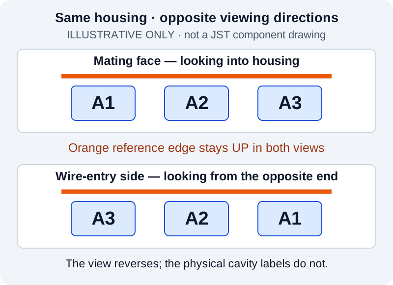
Illustrative view convention only. A1–A3 are example cavity labels, not official pin locations for a JST part. The reference edge stays up in both views; a real drawing must follow its exact component documentation.
Write a connection map that can be checked
The example below is a fictional three-circuit interconnect. Each end has its own mating-face drawing with the reference edge up. In those example drawings, A1–A3 and B1–B3 run left to right. No JST model, voltage rating or equipment compatibility is implied.
| Circuit in this example | End A cavity | End B cavity | Example wire identification |
|---|---|---|---|
| Supply positive | A1 | B3 | Red |
| Supply return | A2 | B2 | Black |
| Enable signal | A3 | B1 | Blue |
The table is the intended electrical connection. A1 connects to B3 because the two hypothetical board interfaces place that function in different cavities. This is not a rule that JST cables should be reversed. If the actual equipment assigns supply positive to different positions, the table must change to match it.
The colors make this example easier to read; they do not prove a circuit's function. Specify any required wire markings alongside the map, and resolve a conflict between color and the approved drawing before manufacture. Where no color convention exists, numbered wire identifiers can be clearer.
Avoid relying on “straight-through,” “reversed” or “same order” without a map. Those terms can describe electrical numbering, a photograph's left-to-right order or the way two housings are placed on a bench. A table with named ends removes that ambiguity.
Include intentional blanks and separate the returns
For housings with unused positions, distinguish an empty cavity from a populated contact with an intentionally unconnected wire. State what should be absent or isolated rather than leaving an unexplained blank in the drawing.
Likewise, signal return, supply return, chassis and shield are not automatically the same net. If the design joins them, show where that connection occurs. Do not ask a supplier to infer it from black insulation or a ground symbol without context. A shield termination may also require a detail beyond the ordinary point-to-point conductor table.
Make verification follow the drawing
Define continuity checks by the approved endpoint pairs, not only by a statement that “all wires conduct.” In the fictional example, the required paths are A1–B3, A2–B2 and A3–B1. A test specification should also identify unintended connections that must be absent. Where the design intentionally joins circuits, the test must account for those joins.
A continuity result alone does not establish correct operating voltage, current capacity, insulation performance or equipment behavior. Resolve the map with the equipment owner before energizing a first article. Additional electrical acceptance tests depend on the application and must be agreed explicitly; this guide does not promise a particular test program for every order.
Keep the drawing revision with the sample and production order. A connector substitution, changed viewing convention or revised board pin assignment can invalidate an otherwise familiar cable. Review what changed instead of approving it solely because the housings still fit.
Turn an uncertain sample into a reviewable request
Send the mating-part references, equipment connector assignment and the current cable drawing if available. Identify which end is A and which is B, define both views, and provide the required connection table. Include a measured sample map only when its method and orientation are known; do not describe an unverified sample as the approved electrical source.
Zeakka supplies alternative connectors. For finished cable assemblies, original JST components may be sourced by exact part number and availability, or unbranded alternatives may be reviewed for the project. Original components are not sold separately. Neither sourcing choice determines your equipment's pinout.
For a known interface, explore custom JST PH cable assemblies or custom JST GH cable assemblies. To resolve a wiring definition, send the two mating references and connection map. A clear view convention and a short, unambiguous map are more useful than additional unlabeled photographs.
Share this article
Help others discover this content