
CABLE ASSEMBLY SELECTION GUIDE
JST PH vs XH: Wire Gauge, Current Ratings and Cable Assembly Selection
PH and XH differ in more than pitch. Compare the wire each terminal accepts, the conditions behind the current rating, and the space the complete connection needs—then define a cable that fits your application.
Already have a PCB? Start with its mating connector. Designing a new interface? Use the specifications below to narrow the choice, not as a finished-harness rating.
Compare specificationsTechnical references checked September 24, 2026.
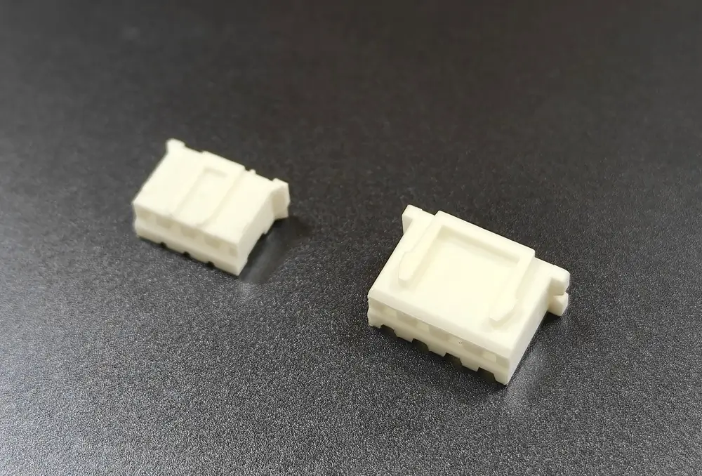
1. Start with the interface, not the family name
An existing board or device
Identify the fitted header or the approved mating part first. A higher published current rating is not a reason to substitute a different family into an existing interface. Obtain the part number, drawing or clear mating-face photos before choosing a housing and contacts.
A new connection
Define load, working voltage, cable length, wire construction and available space together. Then check the terminal, housing and board-header combination. If neither family meets the requirements, evaluate another connector system.
Neither name determines the application: “PH for signals” and “XH for power” are not sufficient selection rules.
2. PH vs XH: the specifications that matter
These are reference values for the original JST series, not a specification for every compatible product or completed cable.
| Parameter | JST PH | JST XH |
|---|---|---|
| Nominal pitch | 2.00 mm | 2.50 mm |
| Published current rating | 2 A AC/DC with AWG 24 | 3 A AC/DC with AWG 22 |
| Published voltage rating | 100 V AC/DC | 250 V AC/DC |
| Series conductor range¹ | AWG 32–24 | AWG 30–22 |
| Series insulation outside diameter¹ | 0.5–1.5 mm | 0.9–1.9 mm |
| Temperature range² | −40 to +105 °C | −25 to +85 °C |
| Standard top-entry assembled height³ | 8.0 mm | 9.8 mm |
¹ The series range combines different contacts. One terminal does not accept the entire range.
² Includes temperature rise caused by current; it is not an ambient-temperature allowance plus unlimited self-heating.
³ Reference top-entry through-hole assembly. Check the exact variant drawing for the installed envelope.
Sources: JST PH datasheet / JST XH datasheet.
3. Select the terminal and wire as a pair
AWG describes conductor size, not the outside diameter of the insulated wire. Two wires with the same AWG can require different insulation-grip conditions. Specify both the conductor and the insulation diameter before accepting a terminal choice.
| Family | JST contact | AWG | Insulation OD, mm |
|---|---|---|---|
| PH | SPH-004T-P0.5S | 32–28 | 0.5–0.9 |
| PH | SPH-002T-P0.5S | 30–24 | 0.8–1.5 |
| XH | SXH-002T-P0.6 | 30–26 | 0.9–1.3 |
| XH | SXH-001T-P0.6 | 28–22 | 0.9–1.9 |
Sources: JST PH datasheet / JST XH datasheet. PH contact table: PDF page 2; XH contact table: PDF page 3.
What this changes in a real RFQ
An AWG 24 request is not complete without the wire construction and outside diameter. Ask the assembler to confirm the chosen contact, wire and crimp tooling together. Do not assume a thicker insulation, a different strand construction or two wires in one crimp is acceptable because the conductor size looks close.
For example, the listed PH contact SPH-004T-P0.5S does not cover AWG 24, although AWG 24 appears in the PH series range. Avoid specifying only “PH terminal” on a production BOM.
4. A 2 A or 3 A connector rating is not the cable rating
The published current figures above include a wire-gauge condition. They are not permission to apply that current to every thinner wire, longer cable or enclosed bundle. Review the complete path: wire, crimps, contacts, board interface and operating environment.
- Load: provide normal current and any startup or peak condition, including duration.
- Length: include the outgoing and return paths when assessing resistance and voltage drop.
- Installation: identify enclosure temperature, bundling and nearby heat sources.
- Validation: agree the operating conditions and acceptance limits before judging suitability.
Long cable? Check the voltage at the load.
Voltage drop follows ΔV = I × R for the circuit being evaluated. A cable can pass continuity testing yet deliver an unacceptable voltage under load. Continuity and short-circuit checks do not establish current-carrying suitability.
Use working-voltage limits for selection. A short-duration dielectric withstand test is not the continuous working-voltage rating. For borderline conditions, request an application review rather than applying an invented universal derating percentage.
5. Check pitch, installed space and mating geometry
Compare the same circuit count when assessing package size. Include the mated connector, wire exit and room for assembly—not only the empty housing. Top-entry and side-entry headers can change the required envelope substantially.
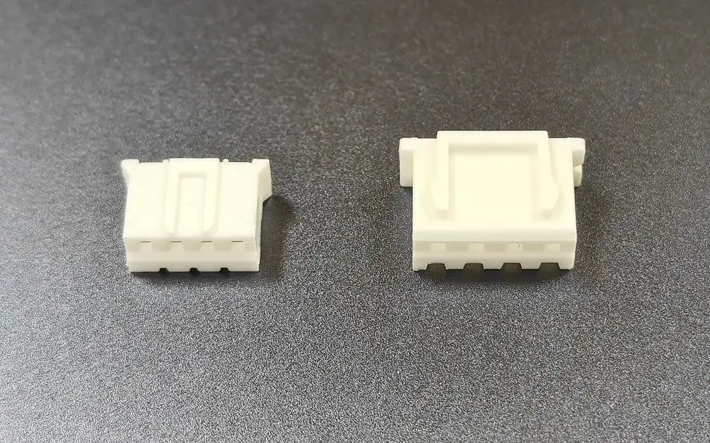
Measure pitch across several positions
For a uniform row, measure between the centres of the first and last positions, then divide by the number of intervals. Four positions contain three intervals. Do not divide the outside housing width by the pin count.
A nominal four-position row spans 6.00 mm between the end centres at 2.00 mm pitch, or 7.50 mm at 2.50 mm pitch. These are calculated pitch spans, not housing dimensions. A perspective photo without a scale cannot provide an accurate measurement.
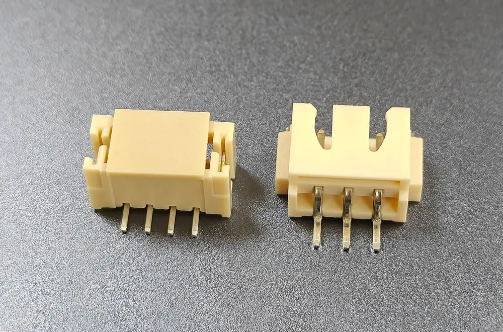
After identification, confirm the header and housing references, orientation and pin numbering. Record whether the drawing is viewed from the mating face or wire-entry side. See the cable pinout and viewing-direction guide for documenting that distinction.
6. Turn the selection into a buildable cable specification
A useful production agreement identifies what is being supplied and how it will be accepted. You do not need every detail to start an inquiry, but unresolved items should be closed before the approved build.
- 1
Identify the components
State genuine JST components or an explicitly identified compatible alternative. Appearance does not establish origin, material, plating or performance. Genuine components can be requested as part of a completed assembly; alternatives need their own supporting specifications.
- 2
Define the assembly
Confirm each end, wire and contact combination, length measurement points, tolerances and pin-to-pin mapping. Include branches, sleeves, labels or other required features. Do not rely on wire colour alone to define a circuit.
- 3
Agree sample acceptance
Check mating fit, dimensions and wiring. Agree crimp inspection and any pull-test requirements against the applicable contact and wire specification. Electrical checks should match the agreed scope, with load or environmental validation where required.
- 4
Align the commercial scope
Confirm sample quantity, first production quantity, component availability, any minimum material buy, lead-time starting conditions and required documentation. These are quotation-specific—not universal promises attached to PH or XH.
Zeakka coordinates sourcing and custom cable assembly requirements. The component selection, manufacturing scope and evidence should be confirmed for your project.
7. Quick questions
Is JST XH 2.50 mm or 2.54 mm?
The JST XH series has a nominal 2.50 mm pitch. A listing described as XH 2.54 mm is not sufficient identification: ask for the actual part drawing and mating reference. Do not force a connector into a mismatched PCB footprint.
Can I replace a PH cable with an XH cable of the same pin count?
Not as a direct mating replacement. Circuit count does not establish compatibility. Check the board header, housing, contacts, pitch and keying. Changing the connector family can also require a different PCB footprint and a new mechanical review.
Can a cable have PH at one end and XH at the other?
A mixed-connector assembly can be specified, but connecting the two families does not increase the rating of the PH end or establish electrical compatibility. Confirm the wire-to-terminal combination at each end, circuit mapping, load and working voltage before production.
Are a male board header and an inline cable plug the same thing?
No. A board header is designed to mount on a PCB. For a cable-to-cable extension, identify the actual inline mating parts rather than specifying only male and female. Any compatible alternative should be identified separately from genuine JST components.
Can I start an inquiry without a drawing or exact part number?
Yes. Send clear connector photos, the approximate cable length, quantity and what the cable needs to connect. Add the electrical load and wire details if known. The remaining specification can be clarified before sample approval; a complete BOM is not required for the first conversation.
Have an interface to match or a cable to define?
Start with photos or a short description. Add length, quantity and electrical requirements if known. A finished drawing or BOM is optional at the inquiry stage.