
JST Connector Wire Gauge and Current Rating: A Cable Selection Guide
Table of Contents
A connector's current rating does not tell you which cable to order. A useful specification connects the exact terminal to the wire construction, circuit load and operating environment. Missing any of these can leave a cable that fits mechanically but fails its electrical or thermal requirements.
Start with the required current at each circuit. Then check the contact's conductor and insulation ranges, the complete current path, and the temperature conditions. The examples below use original JST documentation; they do not establish ratings for unbranded alternatives or a finished Zeakka harness.
Read the wire condition beside the current rating
JST's PH catalog lists 2 A AC/DC with AWG 24. Its GH catalog lists 1 A AC/DC with AWG 26. These are qualified catalog figures, not universal limits for every wire accepted by those families. JST PH catalog, p. 1; JST GH catalog, p. 1.
For example, a smaller conductor may fit a listed contact without establishing that the assembly can carry the headline current. Nor does selecting a thicker conductor authorize an increase above the connector rating. Keep electrical requirements and termination compatibility as separate checks.
If you have not identified the connector, begin with the common JST connector types guide. A family name alone is insufficient for cable selection: obtain the contact part number as well as the housing and mating interface details.
Three contact examples: AWG and insulation diameter must both fit
AWG describes conductor size; it does not specify the outside diameter of the insulated wire. Wires with the same AWG can have different insulation thicknesses, materials and strand constructions.
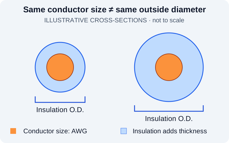
Illustrative cross-sections, not to scale. Conductor size and insulation outside diameter are separate specifications; no actual wire product is shown.
| Original JST contact | Catalog conductor range | Insulation outside diameter |
|---|---|---|
| SPH-002T-P0.5S | AWG 30–24 | 0.8–1.5 mm |
| SPH-004T-P0.5S | AWG 32–28 | 0.5–0.9 mm |
| SSHL-002T-P0.2 | AWG 30–26 | 0.76–1.0 mm |
Sources: PH contact table, p. 2; GH contact table, p. 2. These are termination ranges for the named original contacts, not wire ampacity tables.
Consider a proposed AWG 28 wire with a specified 1.2 mm insulation diameter. It falls within the two listed size ranges for SPH-002T-P0.5S. Its insulation is too large for SPH-004T-P0.5S, despite AWG 28 appearing in that contact's conductor range. The same proposed wire also exceeds the insulation range of SSHL-002T-P0.2.
This is a dimensional screening example, not approval of a particular wire. Check the actual wire specification, diameter tolerance and terminal application requirements before confirming the combination. “AWG 28 cable” leaves too much undefined for production.
Temperature limits include heating under load
Both current PH and GH catalogs specify −40°C to +105°C, including the temperature rise caused by electrical current. The upper figure therefore must not be read as an ambient-temperature allowance with additional self-heating on top. PH specifications, p. 1; GH specifications, p. 1.
As an illustrative thermal budget, 85°C ambient leaves only 20°C to a 105°C ceiling, before allowing for local heating from nearby components. That arithmetic does not establish an acceptable load current or replace the applicable product test requirements. The wire insulation or another component may impose a lower limit.
Specify the temperature around the installed connector, including a warm enclosure, together with the operating duty cycle. A bench sample tested in open air does not reproduce a bundled cable near a heat source. Ask for application-specific evidence when operation approaches a component limit; do not invent a universal percentage derating rule.
Follow the current through the whole assembly
Trace the supply and return paths through the board, mating contacts, terminations, wires, splices and the far-end connector. Each segment needs to support its actual load. The connector family printed on one end cannot qualify the rest of that path.
In a two-wire DC circuit, the supply and return conductors each carry the load current. In a branched assembly, a shared feed or return can carry the sum of simultaneous branch currents. Record those currents explicitly rather than dividing a total equally across the connector's positions.
Cable length also matters. Using the specified conductor resistance and total supply-and-return length, estimate the wire's contribution to voltage drop with V = I × R. Include contact and termination resistance when assessing the full path. Longer cable can consume the voltage budget even when connector selection remains unchanged.
Check continuous load, startup peaks and their duration. If several circuits operate together, validate that loading arrangement and the installed routing. Do not assume parallel contacts share current equally or multiply a catalog rating by the number of positions to create an assembly rating.
Turn the selection into a reviewable cable specification
Send the information needed to evaluate one defined assembly:
- Connector and contact references, position count, pinout and mating interface.
- Wire AWG, material and strand construction, insulation type, outside diameter and temperature rating.
- Finished lengths and tolerances, branches, bundling and installation constraints.
- Continuous and peak current per circuit, shared-return loads and allowable voltage drop.
- Ambient conditions, duty cycle, required verification and original-versus-alternative component requirements.
Zeakka supplies unbranded alternative connectors. For finished cable assemblies, original JST components may be sourced subject to specific part-number availability, or unbranded alternatives can be reviewed for the application. Zeakka does not sell original JST components separately. Original JST catalog values do not qualify an alternative; its actual components and completed assembly require their own supporting specifications and agreed verification. SH and ZH assembly configurations require project review.
For a defined project, review custom PH cable assemblies, custom GH cable assemblies or custom XH cable assemblies, and submit the wire and circuit requirements above with your drawing. For loose alternative components, use the PH connector page.
Share this article
Help others discover this content