
CABLE ASSEMBLY SELECTION GUIDE
Micro-Fit 3.0 vs Mini-Fit Jr.: Choosing a Custom Cable Assembly
An existing connector usually determines the mating family. For a new design, compare the complete connection: space, contacts, wire and operating conditions. Then define the cable around it.
1. Is the mating interface already fixed?
Existing equipment or PCB
Start with the fitted connector or approved mating-part number. Match its row layout, keying, latch and contact system. Do not substitute a different family because its headline current rating looks higher.
A new interface
Define the number of circuits, load, working voltage, installation space and service access. Shortlist a complete mating set, then verify the terminal, wire and thermal limits together.
Micro-Fit 3.0 is a useful starting point when contact spacing is tight. Mini-Fit Jr. is another candidate when its package and available contact options suit the design. Neither family wins without the application details; either may be unsuitable.
2. Micro-Fit 3.0 vs Mini-Fit Jr. at a glance
The part numbers below are original Molex, four-circuit, dual-row examples. Select the exact mating parts and terminals required by your equipment.
Swipe the table horizontally to compare both families.
| Selection point | Micro-Fit 3.0 | Mini-Fit Jr. |
|---|---|---|
| Nominal contact pitch | 3.00 mm | 4.20 mm |
| Four-circuit, dual-row receptacle example | 43025-0400 · 43025 series | 39-01-2040 · 5557 series |
| Cable-side plug example for that receptacle | 43020-0400 · 43020 series | 39-01-2041 · 5559 series |
| Space review | Start here when a finer contact pitch may help; check the complete mated envelope. | Allow for the larger contact pitch; verify the exact housing, latch and wire-exit envelope. |
| Rows, cavities and keying | Confirm the chosen layout and populated cavities. A family name is not a mating specification. | Confirm the chosen layout and populated cavities. The examples here are standard dual-row parts. |
| Terminal and wire | Select the exact contact and its permitted conductor / insulation combination. | Select the exact contact and its permitted conductor / insulation combination. |
| Current suitability | Use the applicable configuration and temperature-rise data; no universal harness rating. | Use the applicable contact-material and configuration data; no universal harness rating. |
References: 43025 housing drawing, 43020-0400 plug, 5557 housing drawing and 5559 plug drawing. Current conditions: PS-43045 and PS-5556-001.
3. Identify the parts, then check the installed space
Ask for the complete part number, including the suffix. If that is unavailable, collect a straight-on mating-face photo, a latch-side view and any marking. Record the number of rows, total cavities and populated positions separately. Treat photos as identification clues until the drawing and actual mating part agree.
An inline plug is not a board header
For example, a 43025-0400 receptacle housing can be paired with the 43020-0400 cable-side plug example above. The 43025 drawing also names board-header series 43045. Likewise, the 5557 drawing names cable-side 5559 and board-header families 5566/5569. Identify the exact header variant when the other side is a PCB; “four-pin male” leaves that choice unresolved.
Pitch is only one dimension
Check the mated length, width and height, board orientation, panel features and latch clearance. Reserve room for the wire exit, bend and fingers or tools needed to disconnect it. A smaller pitch does not guarantee that the finished assembly fits an enclosure.
For a uniform row, centre-to-centre span divided by the number of intervals gives pitch. A four-position row has three intervals; a four-circuit dual-row housing has only two positions per row. Do not divide overall housing width by total circuit count.
Use the linked housing drawings for geometry and mating-series references. Confirm the complete pair and orientation before ordering; matching only the number of cavities is insufficient.
4. Match the terminal to both conductor and insulation
“18 AWG cable” does not fully specify a crimp. The conductor size, stranding and insulation outside diameter must suit the selected terminal and its application tooling. Two wires of the same AWG can have different insulation diameters.
| Family / contact | Conductor sizes | Insulation outside diameter |
|---|---|---|
| Micro-Fit 3.0 43030-0001 | 20, 22, 24 AWG | 1.85 mm maximum |
| Mini-Fit Jr. 39-00-0038 | 18, 20, 22, 24 AWG | 1.30–3.10 mm |
Limits apply to these two contacts only, not the full families. Sources: Molex SD-43030-XXXX Rev N10, 55560000-SD Rev A3 and the 39-00-0038 product specifications. These receptacle contacts do not complete the plug-side BOM.
For example, an 18 AWG request is outside the listed sizes for 43030-0001, although it appears for 39-00-0038. That does not rule out every Micro-Fit contact; it means the proposed contact must change or the wire requirement must be reviewed. The insulation limit still applies.
- Select the actual contact: receptacle or pin, part number, material and plating. A series-level wire range can combine several terminals.
- Check both crimp zones: conductor crimp and insulation support. Confirm the permitted combination against the applicable contact drawing and application specification.
- Review both ends: the wire must suit each terminal on a mixed-end cable. Do not assume two wires may share a crimp unless that exact combination is supported.
If the required wire does not fit, revisit the contact or connector choice. Reducing conductor size to make it fit also changes the resistance and thermal assessment.
5. Evaluate current for the complete circuit
A family-page “up to” value cannot rate your custom harness. Molex’s Micro-Fit dual-row specification separates current data by wire gauge, circuit count and connection type. The Mini-Fit Jr. specification also distinguishes contact materials. Read the applicable table or curve for the actual BOM and its test conditions.
The cited tables use a 30°C temperature-rise criterion under stated test conditions. That rise is not the ambient operating temperature or an extra allowance above the connector’s temperature limit; the application still needs its own thermal review.
Official basis: PS-43045 Rev R, current-rating tables; PS-5556-001 Rev H2, current and temperature conditions.
Describe the load
State normal current per circuit, simultaneously loaded positions, startup or peak current and duration, working voltage and duty cycle. Include shared returns or branch currents.
Describe the installation
State ambient temperature, enclosure airflow, nearby heat, bundling and cable length. Review wire, crimps, mating contacts and PCB termination as one path.
Length still matters after the connector fits
Voltage drop follows ΔV = I × R for the circuit under review. Include outgoing and return conductor resistance. A longer cable or shared return can change the voltage available at the load. Passing continuity and short-circuit checks does not establish acceptable voltage drop or temperature rise.
Agree application validation and acceptance limits where required. Do not multiply a per-contact maximum by the number of positions, invent a universal derating percentage, or transfer original Molex data to an unbranded candidate.
6. Turn the choice into a useful cable RFQ
Start with an email and a short requirement. The following checklist helps close the details as the project develops; it is not a prerequisite for contacting us.
- 1
Lock down each interface
Record End A and End B housings, contacts and actual mating parts. Add row layout, cavity population, latch orientation and any mechanical constraints.
- 2
Define wiring and length
Give every pin-to-pin connection, Pin 1 and the viewing direction at each end. State finished-length measurement points and tolerances, exposed leads, branch lengths and breakout positions. Wire colour alone is not a pinout.
- 3
State load, wire and construction
Add operating conditions, conductor and insulation details, and any jacket, sleeve, strain relief or label requirements. Connection structure and protection are separate choices.
- 4
Keep the sourcing basis explicit
State whether original Molex components are required or unbranded compatible candidates may be evaluated. Identify the actual offered components and their supporting specifications separately.
- 5
Agree sample and commercial requirements
Confirm mating fit, pinout, dimensions and project-specific inspection or load-validation scope. Include sample quantity, production quantity, timing and required documents; availability, MOQ and lead time are quotation-specific.
Zeakka is a China-based trading and sourcing coordination partner, not a factory. Original Molex housings and terminals can be sourced for finished assemblies, subject to exact parts and availability; they are not sold separately. Compatible candidates need their own review. Official Molex specifications do not establish their performance or certification.
Explore the assembly options for each family
Assembly examples, not shown to scale. Confirm dimensions, component origin and electrical ratings in the agreed project specification.
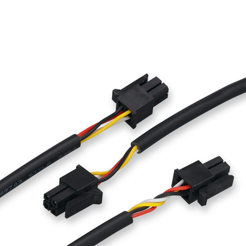
Micro-Fit assembly example · Jacketed cable ends
Micro-Fit cable assembly options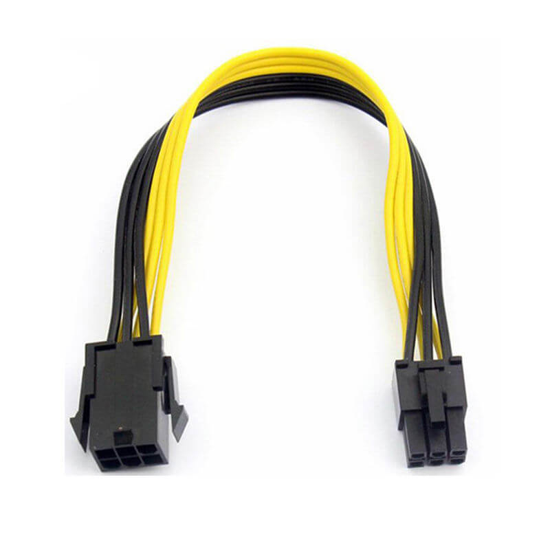
Mini-Fit assembly example · Inline extension
Mini-Fit Jr. cable assembly options7. Common selection questions
Are Micro-Fit 3.0 and Mini-Fit Jr. interchangeable?
No. They are different mating systems with different nominal pitches and geometry. Equal circuit counts or the Molex name do not establish a match. Identify the approved housing, contacts and mating part; changing family can require changes to both ends of the connection and the PCB.
Does a larger Mini-Fit Jr. connector automatically carry more current?
No. Compare the exact contact, wire, loaded circuits and thermal conditions. Published family maximums are not ratings for every part or completed assembly. A larger housing cannot correct an unsuitable crimp, wire or board connection.
Do these specifications also apply to Micro-Fit+, Mini-Fit Max or BMI connectors?
Use the specification for the exact proposed parts. This guide covers Micro-Fit 3.0 and Mini-Fit Jr. examples; Micro-Fit+, Mini-Fit Max, Mini-Fit Sr. and blind-mate (BMI) variants are outside this comparison. A similar family name or matching pitch does not establish mechanical or electrical interchangeability.
Can a custom cable connect the two families?
A mixed-end requirement can be reviewed, with each interface and every circuit identified separately. Such a cable does not make the connector families directly mateable, raise the rating of either end, or prove that the connected devices have compatible pinouts or electrical functions.
Can Zeakka quote original Molex parts and a compatible option separately?
Yes, for a finished cable assembly, subject to exact part selection and availability. Original Molex components are not sold separately. If your project permits unbranded compatible candidates, their drawings, materials, mating fit and required performance are reviewed separately and the agreed sourcing basis is identified in the quotation.
What if I only have photos and no drawing?
Start with your email and a short description. If available, add mating-face and latch-side photos, any part marking, approximate length and quantity. Photos help start identification; exact parts, pinout and acceptance requirements still need to be resolved before sample or production approval.
8. Molex drawings and specifications
These documents apply to the original Molex parts listed below. Check the latest revision for the exact ordered parts when approving a design.
- Micro-Fit dual-row product specification PS-43045, Rev R · November 14, 2025. The dual-row scope is not a specification for every Micro-Fit variant.
- Mini-Fit Jr. product specification PS-5556-001, Rev H2 · June 22, 2026. Use the conditions for the selected terminal and configuration.
- 430250000-SD, Rev A · 43025-0400 receptacle example, pitch and mating-series notes. 43020-0400 product page · four-circuit cable-side plug example.
- SD-5557-003, Rev K1 · includes 39-01-2040 / 5557-04R. 55590020-SD, Rev A4 · includes 39-01-2041 / 5559-04P. Locate your exact part number in each drawing’s part table.
- SD-43030-XXXX, Rev N10 · April 24, 2026, contact 43030-0001. 55560000-SD, Rev A3 · April 14, 2021, contact 39-00-0038. Check the applicable crimp specification and tooling as well as the contact drawing.
Have an interface to match?
Send a part reference, photo or short description. Add approximate length, quantity and load if known. We can help clarify the cable requirements and sourcing basis.
Only email and a short requirement are required to start. Name, company, drawings and attachments are optional.