
Ribbon Cable Pitch Explained: Conductor Spacing vs Connector Pitch
Table of Contents
“Ribbon cable pitch” normally describes the center-to-center spacing of adjacent conductors. A connector drawing may instead quote the spacing of its mating contacts, and a two-row connector can have a grid dimension in two directions. Treating all of these as one number can produce a cable that looks plausible but cannot be terminated or mated correctly.
For an assembly request, record cable conductor spacing and connector contact pitch separately, then identify the exact cable and connector references. Pitch narrows the choices; it does not establish the complete cable specification, the pinout or the current rating.
Three dimensions to keep separate
Scroll sideways to read all columns.
| Dimension | What it describes | Where to verify it |
|---|---|---|
| Cable conductor pitch | Center-to-center distance between adjacent conductors | Cable drawing or specification |
| Connector contact pitch | Center-to-center distance between mating contacts along a stated row | Connector mating-face or interface drawing |
| Connector row spacing | Distance between the rows in a multi-row interface | The same drawing, with its view and dimension directions identified |
The connector housing's outside width is a fourth, different dimension. Insulation edge margins and housing walls mean you cannot reliably recover pitch simply by dividing the overall width by conductor or contact count.
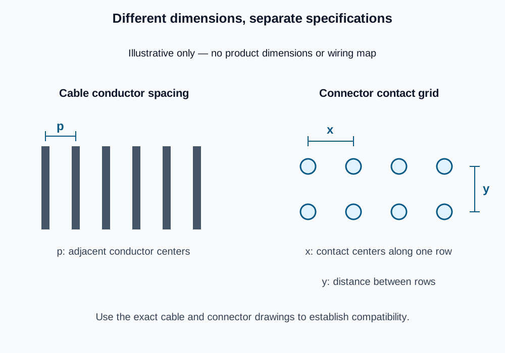
Illustrative geometry only. The two sketches are independent references, not a compatible pair or a wiring diagram. No product dimensions are implied.
Why a 2.54 mm connector can use 1.27 mm ribbon cable
A concrete example is the 3M 891 series drawing. It specifies a 0.100 × 0.100 inch connector grid for 0.050 inch pitch cable: 2.54 × 2.54 mm at the connector and 1.27 mm between cable conductors. Its two-row contact arrangement accommodates a cable pitch that differs from the mating grid.
That relationship belongs to the specified connector design. It is not a universal rule that the connector pitch is twice the cable pitch. Do not apply it to a different IDC family, a single-row connector or an FFC interface. Likewise, the example does not identify the connectors in a sample photograph or qualify an alternative component.
A supplier description saying only “2.54 mm ribbon cable assembly” therefore needs clarification: does that number refer to the cable, the connector, or a board footprint? Ask for both part references and their dimensional drawings before approving a substitution.
Check an unknown sample without inventing precision
Start with readable cable markings and the connector part number. If neither is available, a physical measurement can help identify candidates, but it should be recorded as a measurement with uncertainty, not as the approved drawing dimension.
Where the conductor centers can be identified, measure across several equal intervals instead of one. If the center-to-center span from conductor 1 to conductor 11 is approximately 12.7 mm, there are ten intervals, giving an estimated pitch of 12.7 ÷ 10 = 1.27 mm. This is a measurement example, not a dimension assigned to the supplied sample.
Keep the cable flat, avoid stretching it and use a suitable measuring tool. Surface ribs may help locate conductors, but verify the construction rather than assuming that every visible line is a conductor center. A perspective photograph, ruler placed at another depth or housing edge is not a reliable precision datum. Do not damage an assembled sample merely to expose the conductors.
Matching pitch is only the first compatibility check
For an IDC termination, also check the selected contact's accepted conductor size, solid or stranded construction and insulation dimensions. The connector's specified cover, termination method and strain relief may affect the complete build. The board-side mating geometry, keying and contact count need a separate check.
A cable with the right pitch but the wrong insulation or conductor construction is not automatically suitable. A correctly terminated cable can still have the wrong equipment pinout. Use the pinout and polarity guide for numbering and view conventions, then approve the end-to-end map against the equipment requirements.
Pitch alone also says nothing sufficient about current capacity, voltage, bend endurance or signal performance. Those depend on the selected parts, construction and operating conditions. A thinner-looking or finer-pitch cable is not an interchangeable replacement just because it fits the available space.
Turn the measurements into a purchase specification
For custom flat ribbon cable assemblies, supply the cable reference and conductor spacing, conductor count and construction, connector references at each end, finished length and its datum, and the approved connection map. Label any measured value that still needs confirmation. If you need unterminated cable, use the bulk flat ribbon cable page instead.
Zeakka is a trading and sourcing partner. We coordinate review of the specified build and suitable supplier options; an estimated pitch or similar photograph does not confirm component interchangeability. Send the available drawing or sample details so unresolved dimensions can be identified before a quote is scoped.
Share this article
Help others discover this content