
IDC vs Crimp Termination for Ribbon Cable Assemblies
Table of Contents
Choosing between IDC and crimp termination starts with the cable, mating connectors and required assembly layout. Both methods can be suitable when the components and process are specified together. Neither provides a universal advantage in reliability, current capacity or total cost.
This guide concerns round-conductor ribbon cable assemblies. FFC and flexible printed circuits require their own interface and termination review; their flat shape does not make them equivalent to separable round-wire ribbon cable.
What changes at the termination?
With IDC termination, a compatible insulated conductor enters a contact slot that displaces the insulation and establishes contact. Ribbon connector systems such as TE AMP-LATCH can terminate multiple conductors together without stripping each wire separately. Cable positioning and the specified assembly procedure still matter. TE AMP-LATCH termination overview
With the individual wire crimp termination considered here, each prepared conductor is joined to a specified terminal using compatible tooling, and the terminals are installed in the appropriate housing. The preparation and acceptance criteria depend on the terminal system. Molex's crimp guidance treats wire preparation, terminal geometry and tooling setup as parts of one controlled process. Molex introduction to crimp technology
The methods can also appear at opposite ends of one assembly. Such a design needs a confirmed cable and termination combination at both ends; it is not automatically feasible because each connector accepts the same nominal wire gauge.
When an IDC layout is worth reviewing
An IDC solution is a useful candidate when the mating interface already uses a ribbon connector and the conductors can remain together at the termination. Review connector orientation, cable exit, cover and strain-relief clearance, and any intermediate connectors required by the design.
Mass termination can reduce individual wire preparation, but a purchasing decision should use the supplier's actual assembly process and quote. Connector availability, tooling, test coverage and production quantity can change the result.
The cable must fit the contact system. For example, TE's Micro-MaTch product data identifies both wire size and a compatible insulation diameter range. These are part-specific constraints, not optional details or universal IDC limits. TE Micro-MaTch product example
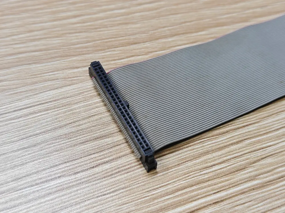
Ribbon connector and cable-entry detail from a supplied sample. Appearance does not establish the permitted wire range or the termination's inspection results.
When individual crimped ends are worth reviewing
A crimped end may suit a specified wire-to-board housing, separated cable ends, or a layout that routes individual conductors to different positions. First confirm that the chosen ribbon construction permits separation and preparation without unacceptable damage.
Some cables explicitly support this: 3M describes its 3365 series as zippable for branching or discrete termination. That is evidence for the named cable family, not permission to split every ribbon cable. Even with a separable cable, the resulting wire still has to satisfy the selected terminal's requirements. 3M 3365 cable construction
Where the required wire sizes, branches or termination combinations do not fit a suitable ribbon construction, review a custom discrete-wire cable assembly as a separate design option.
Specify the complete combination
Scroll sideways to read all columns.
| Review item | IDC end | Individual crimped end |
|---|---|---|
| Cable | Conductor spacing, gauge, strand construction, insulation material and dimensions permitted by the connector specification | Approved wire construction, gauge and insulation outside diameter; suitability after separation from the ribbon |
| Components | Exact connector, cover, strain relief and mating part | Exact terminal, housing and mating part; any specified secondary retention parts |
| Process | Compatible termination equipment, positioning and closure requirements | Approved tool or applicator, strip length, crimp dimensions and terminal insertion requirements |
| Acceptance | Inspection and termination criteria from the applicable connector instructions | Inspection and crimp criteria from the applicable terminal and tooling instructions |
Molex directs users to the Application Tooling Specification for crimp height, pull force and strip length. The relevant document must match the tool and terminal being used. A generic crimp dimension or a tool selected only by wire gauge is insufficient. Molex application tooling guidance
Compare quotes against the same acceptance plan
Ask suppliers to identify the cable, connectors, terminals and proposed tooling rather than quoting only “IDC” or “crimp.” Record any substitution and obtain review before it becomes the production configuration.
Define the drawing revision, cable lengths and tolerances, end preparation, strain relief and inspection requirements. Agree which mechanical checks are needed and how they will be sampled. Establish electrical test coverage for the finished assembly. A continuity result alone does not prove termination strength or service-life performance.
Cost comparisons should include component sourcing, preparation, assembly, tooling or setup, and agreed testing. For serviceability, check the actual connector's mating and terminal-removal instructions; neither termination method guarantees that an assembly is field-repairable.
Send a project-specific request
For custom flat ribbon cable assemblies, send Zeakka the mating part numbers, cable specification, drawing and required operating conditions. As a sourcing and coordination partner, Zeakka can review the proposed combination with suppliers and clarify unresolved details before quoting.
Use the cable assembly RFQ checklist, then contact Zeakka with the available files. If you are still deciding between terminations, identify the fixed requirements and the details open to supplier review.
Share this article
Help others discover this content