
Case study · Canada · GPS/AVL harness sourcing
Resolving Connector and Pinout Ambiguity in a GPS/AVL Harness Project
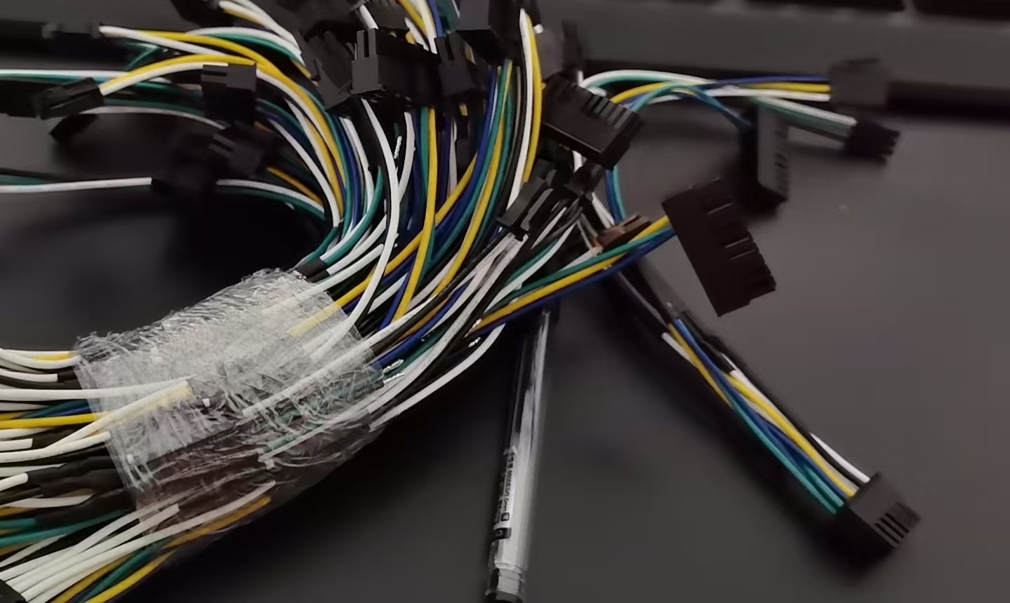
A Canadian GPS/AVL customer approached Zeakka with drawings, a bill of materials and reference images for an initial requirement of approximately 20 harnesses. The task was to turn those inputs into an agreed configuration that a supplier could quote and produce.
- Customer
- Canadian GPS/AVL business
- Initial project
- 20-piece harness order; shipment confirmed
- Separate project
- 300 pieces of a different harness design; receipt confirmed
- Zeakka's role
- Sourcing, specification clarification and supplier coordination
The reference material contained a consequential mismatch: the connector housing shown for P4 differed from the connector specified in the bill of materials. Resolving that discrepancy also required a clear decision on wire positions. Zeakka coordinated the questions, supplier options and customer approvals before the 20-piece order was shipped.
Starting with the project inputs and quantity
The customer's drawings, BOM and reference images provided the starting point for quotation. Supplier discussions compared original-brand components with unbranded compatible alternatives and considered the different quantity thresholds attached to those options. A separate quotation was also prepared for the customer's 20-piece requirement.
This gave the customer a basis for reviewing the sourcing options alongside the intended order quantity. The customer accepted the quotation, and the initial harnesses were made using the agreed unbranded compatible alternatives. The connector selection and finished harness configuration still required clarification: a reference image alone could not settle every detail of the assembly.
Resolving a conflict between the BOM and reference image
During clarification, the P4 housing in the reference image was found to differ from the connector identified in the BOM. Using one source without checking the other would have left two competing instructions for the same interface.
Zeakka raised the discrepancy with the customer. The customer confirmed that the correct connector was the one specified in the BOM. That response established which project input should govern the P4 connector selection, rather than leaving the supplier to infer the intended housing from the image.
Recording the wiring and finish decisions
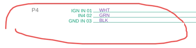
After the connector change, Zeakka supplied two P4 wiring arrangements for the customer's review. The customer selected one drawing and explicitly confirmed that Position 1 should use the white wire. The selected project drawing provided the basis for the remaining wire positions.
The approval was specific to this harness project. It should not be read as a universal GPS/AVL pinout or a connector manufacturer's standard viewing convention. For another assembly, the connector, drawing orientation and required wire positions would need their own confirmation.
The reference image also showed transparent tubing. Zeakka asked about using black heat-shrink tubing instead, and the customer approved that change. Connector selection, wire positions and tubing appearance were therefore addressed as separate decisions, with an explicit response for each issue.
Not selected
Position 1: black wire
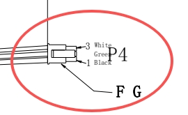
Customer-selected arrangement
Position 1: white wire
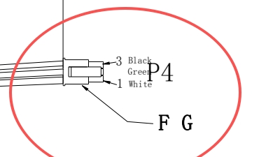
Cropped excerpts from the two drawings discussed by email. Open either image to inspect its original linework. The labels above describe this project's decision, not a universal connector pinout.
| Project position | Wire colour |
|---|---|
| 1 | White |
| 2 | Green |
| 3 | Black |
Text summary of the selected drawing, not a connector-face view or an electrical test record.
Clarifying a separate 300-piece harness design
The same customer also initiated a 300-piece project for a different harness design. Its initial inquiry did not specify the wire gauge. Zeakka requested that missing detail, and the customer confirmed 20 AWG before the remaining freight and commercial details were settled.
This separate order was made using the agreed unbranded compatible alternative component option, and customer receipt of the 300 pieces has been confirmed. It was a different design, so the quantity should not be interpreted as a production repeat of the initial 20-piece harness.
Project outcome
For the initial order, the correspondence confirms shipment of 20 harnesses after the connector, wiring and heat-shrink decisions were agreed. It does not establish customer receipt or equipment validation for that order.
For the separate 300-piece design, the confirmed result is customer receipt. Across the two projects, Zeakka's contribution was to coordinate sourcing and production with suppliers while bringing conflicting or missing specifications back to the customer for a decision.
Have a harness drawing or BOM to review?
Send your drawing, BOM, reference images and target quantity. Include any known connector requirements, pinout details and wire gauge so Zeakka can identify open questions and coordinate a project-specific quotation.