
Cable Assembly Connection List Template: Record Every Conductor and Endpoint
Table of Contents
A connection list identifies the conductor or bond between two named endpoints. It gives a drawing reviewer, assembly supplier and test-program author a shared record to discuss. A useful list also explains the positions that have no wire, the drawing view behind each endpoint name, and any splice or shield connection that cannot be understood from a simple connector-to-connector pair.
Download the editable connection list and fictional example. The workbook contains a blank sheet and an EX-CL-01 example. Amber cells are editable. White check columns flag selected recording problems. These checks compare the information entered; they do not establish that the required circuit, component combination or assembly is correct.
Map physical segments, shared nets and unused positions
Fictional EX-CL-01. Lines represent named connections, not connector-face geometry, actual routing or a qualified shield termination.
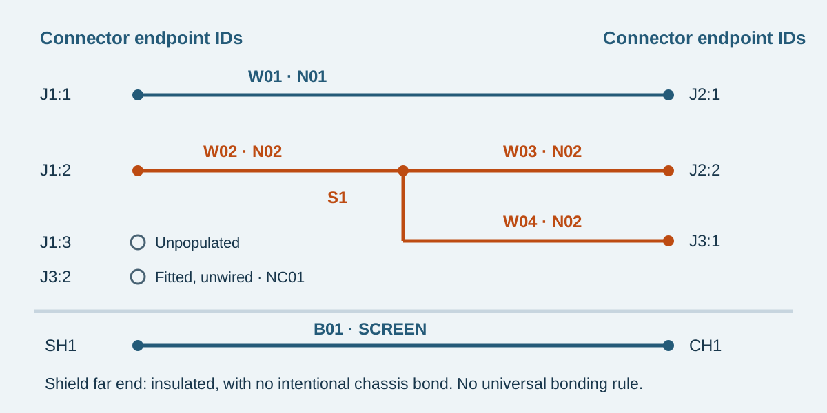
Conceptual illustration. Fictional examples are not approved product configurations, tooling instructions or inspection results.
Set one assembly and revision boundary
Identify the finished assembly, its revision, the controlling drawing and the connection-list revision before entering rows. Record the reviewer and the current review status as ordinary editable fields. Keep any unresolved question visible in the notes associated with the affected endpoint.
Use the cable assembly BOM template for component identities and quantities. Use this connection list for the relationships between those components. A wire specification reference should resolve to the same BOM or drawing package, rather than becoming a second uncontrolled description of the material.
Agree which document controls if the drawing, connection list and sample disagree. Do not quietly select the most convenient version. The workbook does not assign contractual precedence or release an assembly.
Register endpoints before listing conductors
An endpoint name combines the assembly reference with the actual cavity or connection identifier. For example, J1:1 means cavity 1 of J1 in this fictional record. It does not mean the leftmost position in every view. Use the exact component drawing to establish the real numbering.
Scroll sideways to read all columns.
| Endpoint field | What to record | Why it matters |
|---|---|---|
| Endpoint ID | A unique identifier such as J1:1, S1 or CH1 | A cavity number alone is ambiguous when several connectors exist |
| Type | Connector, splice, shield or chassis point | A shared splice node is reviewed differently from repeated use of one terminal |
| Disposition | Connected, unpopulated or isolated | A blank wire row cannot explain whether a position was intentionally omitted |
| Expected net | The electrical network label, or N/A for an unpopulated cavity | Related branches remain associated even when their physical wires differ |
| View reference | Drawing sheet, view and orientation reference | A table does not preserve a photograph's viewing direction by itself |
| Document reference | The controlled drawing or definition | The endpoint must be traceable to the intended assembly revision |
| Detail | Population, bond or open-question information | Conditions stay attached to the endpoint they affect |
The pinout and viewing-direction guide explains how to label connector views. This workbook supplies the record to accompany those views; it does not generate a manufacturer cavity drawing.
In this template, unpopulated means no contact is installed at that connector position. Isolated means an identified point has no conductor or bond assigned in this list; any fitted contact and required isolation must still be defined by the drawing. These are recording conventions for this workbook, not universal connector-industry definitions.
Keep a physical wire ID separate from a net label
Assign a unique ID to each physical conductor segment or deliberate bond. Several wires may share one net label. A splice can therefore appear as the endpoint of several rows without implying several unrelated electrical networks.
The Cirris CR manual, section 9.6, distinguishes test instructions from the networks derived from connections. Its description helps explain why a wire row and an electrical net are different records. It does not make this workbook a Cirris import file or describe Zeakka's equipment.
The workbook uses one row per two-ended segment. A branched net is represented by separate segments meeting at an explicitly registered node. Do not place a comma-separated list of three connector cavities in one From or To cell. That would prevent the endpoint checks from resolving an exact identifier.
Follow the fictional EX-CL-01 example
EX-CL-01 revision A is a teaching example. All EX document and wire references are invented and are not orderable components or approved production instructions.
Scroll sideways to read all columns.
| Segment / bond ID | From | To | Net | Purpose in the example |
|---|---|---|---|---|
| W01 | J1:1 | J2:1 | N01 | One direct conductor |
| W02 | J1:2 | S1 | N02 | First leg of a shared node |
| W03 | S1 | J2:2 | N02 | Second leg |
| W04 | S1 | J3:1 | N02 | Third leg |
| B01 | SH1 | CH1 | SCREEN | Defined shield-to-chassis bond |
S1 is one splice node with three attached conductor ends. The net N02 includes J1:2, S1, J2:2 and J3:1. The table does not authorize three wires in one connector contact; the construction of S1 belongs in the associated splice detail.
J1:3 is explicitly unpopulated. J3:2 is recorded as a fitted but unwired contact with its own isolated net label NC01. Neither position should acquire a wire merely to make the number of listed positions look symmetrical.
SH1 identifies the shield connection, and CH1 identifies the specified chassis attachment point. The shield detail says that the far end is insulated and has no intentional chassis bond. It does not call the far end electrically isolated from the rest of the continuous shield. This is a fictional single-end bonding requirement, not a general recommendation for electromagnetic compatibility. Select the actual shield termination through the equipment design review, using the shielded-cable guide for the questions to resolve.
Read the checks without treating them as approval
Each used conductor row checks its ID for duplication, confirms that From and To each occur once in the endpoint register, rejects a pair with the same endpoint at both ends, and compares the row's net label with both registered endpoint labels. A partially entered row stays visibly incomplete.
The endpoint register counts appearances in both the From and To columns. An unpopulated or isolated point with an attached row is flagged. A connected point with no row is flagged. Repeated use of an ordinary terminal is marked for review, while a splice expects at least two attached segments. These are documentation checks; they do not evaluate permitted wire combinations, crimp geometry or circuit function.
Try changing W04's To value from J3:1 to the unpopulated J1:3. The endpoint remains a known identifier, but the population check and net comparison expose the conflict. Duplicating W01 as another segment ID flags both occurrences. Leaving a required net label empty also produces an explicit message.
Conversely, a wrong connection can escape these checks when its entered labels are internally consistent. A missing endpoint cannot be discovered if it was never registered. Compare the complete register against every cavity in the controlling drawings and review the whole network independently.
Extend and hand over the record
The file reserves 12 endpoint rows and 16 conductor or bond rows. Keep unused rows entirely blank. Use consistent identifier spelling and no leading or trailing spaces. Checks are case-insensitive. Do not sort just one column of a record.
To exceed these limits, extend the endpoint and conductor tables, copy their check formulas and validation, and update every bounded register and conductor range. Check the first added record with a deliberate duplicate and an unknown endpoint before using the extended file. Adding a row of text beyond the checked area does not extend the logic.
Supply the connection list with its numbered views, BOM, dimensional drawing and review status. Keep finished-length requirements and wire-cut definitions in their referenced drawing details; this file does not calculate cutting allowance.
A test program needs its own fixture mapping and validation. Cirris's Fast Attach explanation illustrates the separate relationship between connector pin names and tester-interface wiring. A worksheet with matching labels cannot prove that relationship or replace the agreed continuity, short-circuit and other test requirements.
Common questions
Can I start before the cavity numbers are confirmed?
Yes. Use a clearly provisional endpoint description in the review package and mark the associated view or identity unresolved. Do not present an invented number as a confirmed cavity ID. The file's checks cannot resolve that engineering question.
Is this also a test-program file?
No. It is an editable definition and review record. Translate an approved connection definition into the selected test system, verify fixture-to-assembly mapping, and validate the resulting program separately.
Can two wires share one connector cavity?
Only where the exact contact, wires and termination method are permitted and approved. The workbook flags repeated use of an ordinary endpoint for review; a shared net alone does not authorize a multi-wire crimp.
Does a clean check column mean the harness is ready to build?
No. It means the particular recording checks did not find the conditions they test. The full drawing, parts, materials, dimensions, network definition and required approvals still need review.
Send the list with the views it references
Contact Zeakka with the current connection list, connector-view drawings, BOM and requested quantity. Identify unresolved positions and the person responsible for confirming them. Zeakka coordinates sourcing and supplier review for custom discrete-wire cable assemblies. Feasibility and component selection are confirmed by project; original JST and Molex parts are considered within finished assemblies, not supplied as loose original parts.
Share this article
Help others discover this content