
How to Specify Cable Assembly Length and Tolerances
Table of Contents
A cable described as “300 mm long” can be measured between connector mating faces, between housing exits, or before terminals are attached. Those definitions do not produce the same assembly. For a useful quotation and a repeatable incoming inspection, specify the endpoints, measurement condition and permitted length range together.
Start with the installed route and the features that must reach their positions. Then turn that requirement into dimensions that both the supplier and your inspector can reproduce. A nominal length alone leaves too much to interpretation.
Choose the endpoints before choosing the number
Use a marked drawing with identifiable reference surfaces. “Connector to connector” is insufficient when a housing has a latch, projecting nose, boot or angled cable exit.
Scroll sideways to read all columns.
| Length definition | What the drawing must identify | What it does not establish |
|---|---|---|
| Mating-face to mating-face | The exact mating reference plane at each connector, orientation and measurement path | Exposed wire length or installed routing clearance |
| Housing-exit to housing-exit | The selected rear face or exit plane at each end; whether boots are included | Overall connector-to-connector envelope |
| Cut-wire length | The conductor endpoints and the manufacturing stage at which length is specified | Finished length after crimping, insertion and routing |
A housing rear face and the end of a strain-relief boot are separate references. Label the one you intend. For a right-angle connector, distinguish length measured along the cable path from a projected distance between reference planes.
Molex's Cable Assembly Design Guide, page 18, recommends referencing length dimensions from connector back faces where possible. Its page 7 also discusses overall and branch length tolerances. These are manufacturer-specific design recommendations, not universal acceptance limits or Zeakka commitments. See the official Molex guide.
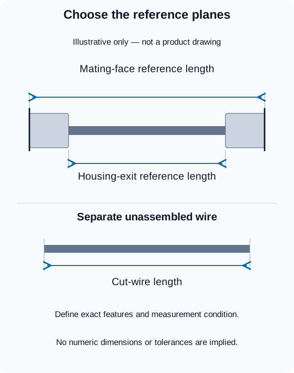
Illustrative reference locations only. Define the exact features and measurement condition on your assembly drawing; these are not dimensions of a supplied product.
Separate finished dimensions from termination details
Specify the finished assembly dimension needed for fit. Let the production method account for the wire consumed inside each termination unless your controlled design also requires a cut-wire dimension.
For an unterminated end, show whether the endpoint is the conductor tip or the insulation edge. Call out strip length separately. For a ring terminal, a mounting-hole center may be the useful installation reference; for another termination, a different feature may be appropriate. Name the feature rather than using “end of terminal.”
If several conductors leave one jacket, dimension their exposed lengths individually when they must reach different locations. Identify the jacket strip-back point separately from the connector face. Adding a boot, changing a housing or changing a terminal can require a dimension review even when the nominal cable length stays unchanged.
Define the measurement condition
For a flexible straight assembly, propose a measurement with the cable supported on a flat surface and gently arranged naturally straight, without stretching the conductors or pulling on the connectors. Agree this condition with the supplier. Do not assume that pulling a cable taut is equivalent to measuring it in its relaxed state.
State whether the assembly is unmated or held in a specified mating fixture. Identify how connectors are oriented and which features locate against stops. If a controlled preload, conditioning period or temperature is necessary for a sensitive design, define it in the inspection method rather than leaving the operator to choose.
Do not straighten a formed or deliberately coiled assembly against its intended geometry. Define its free-state shape or inspection fixture instead. With a branched harness, distinguish measurement along a branch from the straight-line distance between connectors laid on a table. A photograph with a ruler can support the record, but it cannot resolve hidden or undefined endpoints.
Dimension branches and constrained locations
A harness can meet its overall length requirement and still place a branch too early. Mark a reproducible breakout reference, such as a defined sleeve edge or a point located by the agreed fixture. An indistinct place where loose wires separate is difficult to inspect consistently.
Give the trunk-to-breakout distance and the required branch lengths, with their own endpoints and limits. Locate clips, grommets and protective sleeves when installation depends on them. A sleeve edge should only serve as a datum if its position is itself controlled.
Avoid making every segment and the overall sum independently critical without checking consistency. If an overall dimension is only informative, mark it as a reference. If it controls fit, review how the allowed variation of the contributing dimensions affects it.
Set tolerances from the space available
Determine the shortest acceptable assembly and the longest acceptable assembly in the actual route. Consider connector access, service loops, moving parts and available space for excess cable. Keep the required bend radius tied to the selected cable and installation requirements; extra length does not justify a sharp bend near a termination.
The acceptable range may be symmetric or asymmetric. Do not automatically apply a percentage, a catalog table or the drawing's general tolerance to every flexible length. Identify critical dimensions and ask the proposed supplier to confirm feasibility, inspection method and any effect on cost or lead time.
Illustrative example only: suppose a fictional design review establishes an acceptable housing-exit-to-housing-exit range of 300–310 mm. The drawing could state 305 ±5 mm, or 300 +10/−0 mm, using the same endpoints and conditions. Both describe that range. Neither value is a recommended tolerance for your cable or evidence of Zeakka's production capability.
Make the quotation and inspection use the same definition
Before ordering, put these items on the controlled drawing or its linked inspection note:
- Dimension IDs, units, endpoint references and assembly revision.
- Nominal values with explicit limits for the dimensions that control fit.
- Cable arrangement, connector orientation and any required fixture.
- Separate branch, strip-length and protective-component requirements.
- Supplier confirmation of the agreed dimensional requirements and inspection scope.
Use the RFQ checklist for the wider quotation package. Keep circuit assignments in the pinout and viewing-direction guide; a dimensional check cannot confirm wiring. When samples arrive, record actual measurements against the agreed drawing through the sample approval checklist, then validate routing in your equipment.
Zeakka is a trade and sourcing partner. Send your dimensioned drawing or marked sketch to discuss the length definition, unresolved fit requirements and supplier confirmation needed for your project.
Share this article
Help others discover this content