
Cable Assembly Strain Relief: Overmolding, Heat Shrink and Mechanical Clamps
Table of Contents
Cable assembly strain relief should control where pulling and bending loads go. A neat sleeve or substantial molded body is not enough: the design needs a defined load path, enough room for the cable to bend, and access appropriate to the maintenance plan.
Overmolding, heat shrink and mechanical clamps solve different parts of that problem. They can also work together. Choose them around the installed cable, not just the connector photographed on a bench.
Start with the load path
Trace a pull from the exposed cable toward the electrical connection. Which feature takes that force: the cable jacket held by a clamp, a molded connection to the housing, or individual wires entering their terminals? Decide where the load should transfer into the connector body, bracket or enclosure before choosing a covering.
Axial retention and bend control are separate requirements. A clamp may resist cable sliding while leaving a sharp bend at its edge. A flexible boot may spread bending over a longer distance without meeting the required axial retention. Check both functions.
For example, inside a fixed enclosure, a jacket clamp on a bracket can carry installation loads while a short relaxed wire section reaches the connector. At a frequently handled external lead, the connector exit may also need a controlled transition into the flexible cable. These are design examples, not validated Zeakka configurations.
Compare the three options
Scroll sideways to read all columns.
| Option | Useful role | Main design question | Maintenance implication |
|---|---|---|---|
| Overmolding | Defined connector exit and integrated support | How does the molded body retain the cable and distribute bending? | Enclosed terminations are difficult to inspect or rework |
| Heat shrink | Compact insulation, bundling or transition protection | Does this exact tubing and installation provide the required retention? | Replacement normally requires cutting off the sleeve and access for new tubing |
| Mechanical clamp | Transfer cable load to a bracket, housing or enclosure | Will the approved diameter range and clamping method retain the cable without damage? | A removable clamp can allow cable replacement if fasteners remain accessible |
Overmolding: design the exit, not only the body
An overmold can connect a cable jacket to a defined connector-side structure and shape the bending transition. Molex describes this role for its custom overmolded assemblies; that is a manufacturer-specific example, not evidence that every molded cable has equivalent performance. See Molex custom cable assembly solutions.
Review the exit angle, transition length, surrounding clearance and material stiffness together. A long boot still needs space to flex. A bulky body can obstruct a latch or force the cable against an enclosure wall. The jacket, molded material and retention geometry must be assessed as a combination; appearance does not establish adhesion or load capacity.
Choose this route when a defined external shape and protected termination justify the tooling and reduced repair access. Our cable overmolding process guide covers manufacturing steps; this decision begins with the installed geometry.
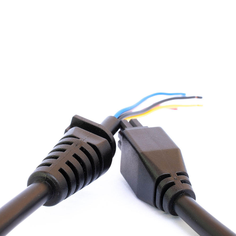
Visible molded exits and ribbed transitions. The photograph does not establish a material, pull rating or IP rating.
Heat shrink: specify its actual job
Heat shrink can provide insulation, finish a sleeve end or protect a transition. A sleeve around a wire bundle does not, by itself, anchor that bundle to a connector or enclosure. State whether the tubing is cosmetic finishing, mechanical protection, sealing or a qualified part of the strain-relief design.
Adhesive-lined products can add sealing functionality. For example, TE describes ATUM tubing as using an internal adhesive that flows during heating and bonds to suitable substrates. This statement applies to that product family, not all heat shrink. See TE ATUM tubing.
Specify the exact tubing, substrate compatibility, installation conditions and overlap. Check whether it can pass over an already fitted connector. Do not label an assembly waterproof merely because tubing has recovered tightly around it.
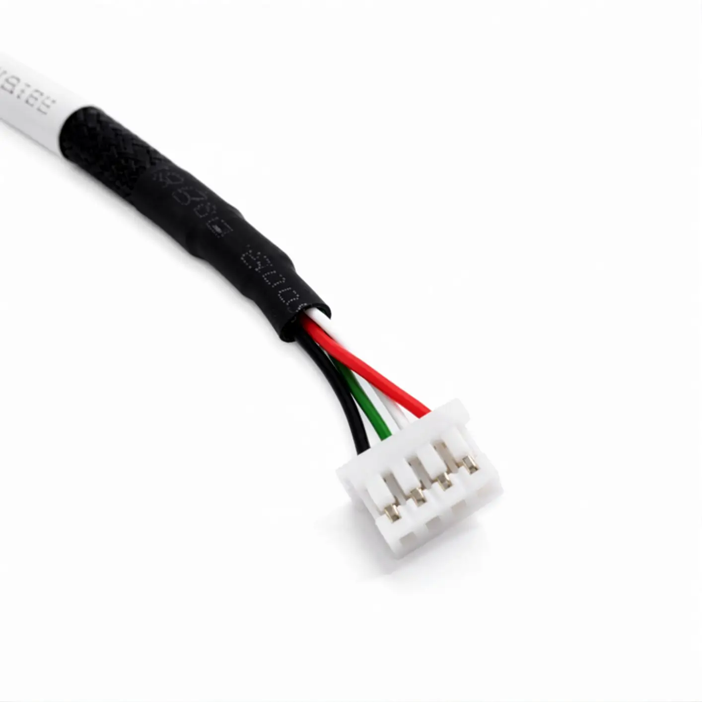
Heat shrink finishing a braided sleeve before individual wires leave the bundle. This view does not demonstrate structural anchoring or sealing.
Mechanical clamps: provide a controlled anchor
A clamp can provide a direct load path into a structure while leaving the electrical connection accessible. Match the selected clamp to the actual cable diameter and tolerance, jacket and installation method. Define the contact area, edge condition, fasteners and any supplier-specified tightening requirement; excess compression is not a substitute for correct sizing.
Keep tool access and replacement clearance on the drawing. For discrete wires without an overall jacket, do not automatically copy a clamp arrangement developed for jacketed cable. Review how the bundle will be held and how individual wire insulation will be protected.
Separate fixed routing from repeated motion
A static connection may move during assembly or servicing even when it stays still in operation. Identify those movements as well as continuous flexing, vibration or twisting. Position anchors so the cable can follow its intended path without being pulled taut across terminals.
For moving systems, use the selected cable and carrier manufacturer's instructions for bend radius and anchor placement. Igus describes integrated strain relief supported by tests on its chainflex cables and notes that anchoring exceptions are application-dependent. Its guidance should not become a universal spacing rule for other cables. See igus strain relief guidance.
Record the moving section, fixed section and available space in the installed position. A boot, sleeve or clamp does not establish a cable's continuous-flex capability.
Keep sealing and strain relief as separate requirements
An overmold is not automatically an IP rating, and heat shrink is not automatically a waterproof barrier. IEC 60529 classifies degrees of protection provided by enclosures; it does not assign a rating simply because a particular assembly process was used. See IEC 60529.
Define the required environmental performance for the actual configuration, including relevant mating interfaces and cable entries. Agree how it will be verified. Mechanical retention and sealing may share features, but satisfying one requirement does not demonstrate the other.
Send the installed arrangement with your RFQ
Include a sketch showing anchor positions, cable exit, moving section and clearance, plus cable construction, diameter tolerance, service access and required pull or flex conditions. Use the cable assembly RFQ checklist to organize the remaining electrical and commercial information.
Zeakka is a trading and sourcing partner. We coordinate specification review, suitable factory quotations and samples; project feasibility and validation scope require confirmation. For a molded solution, start with custom overmolded cable assemblies. Send the application details before treating any protective finish as an approved strain-relief design.
Share this article
Help others discover this content