
Crimp Height, Pull Force and Cross Section Evidence
Table of Contents
A crimp report with a neat photograph and a “PASS” stamp can still leave a buyer unable to approve the work. The missing information is often the link between the measured specimen, the terminal and wire used, and the applicable acceptance requirement.
Crimp height, terminal-to-wire pull force and a prepared cross section answer different questions. Review them as related evidence for one defined process. Do not treat the largest pull number or the most attractive image as the deciding result.
Three forms of crimp inspection evidence
Illustrative specimen groups, not a real inspection report or acceptable crimp profile.
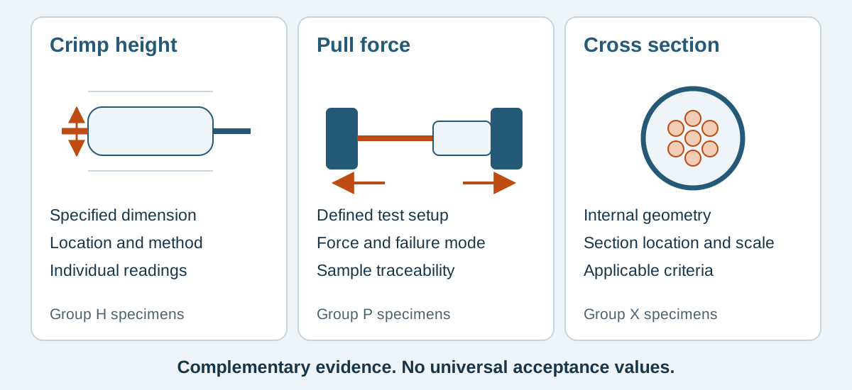
Conceptual illustration. It does not depict an approved product configuration or test result.
Establish what was built and what was required
Before reading measurements, identify the terminal manufacturer and full part number, wire specification and lot, conductor construction, tooling identity, assembly revision and specimen labels. The report should identify the applicable instructions and the origin of its acceptance criteria.
For an alternative terminal, use the alternative manufacturer's applicable process requirements. A terminal that resembles an original branded contact does not inherit its crimp settings, qualifications or ratings.
Keep the document hierarchy clear. A project inspection plan determines what evidence to collect and when. It should reference the relevant acceptance requirements rather than create an undocumented crimp limit.
What the three forms of evidence show
Scroll sideways to read all columns.
| Evidence | Useful review question | What you still need |
|---|---|---|
| Conductor crimp height | Was the stated formed dimension measured by the specified method? | Applicable range, measurement location, tool and specimen identity |
| Terminal-to-wire pull result | What load and failure mode occurred under the stated test method? | Specimen preparation, fixture, loading conditions and applicable criterion |
| Prepared cross section | What internal geometry is visible at this particular section? | Section location, preparation, scale, evaluation criteria and specimen identity |
Molex's Introduction to Crimp Technology defines conductor crimp height between the formed top and the bottom radial surface, excluding extrusion points. It describes measurement at the crimp center to avoid the bellmouth. The same guide distinguishes the conductor crimp from the insulation grip and describes conductor pull testing without the insulation grip's contribution.
That is why an ordinary outside measurement across the wrong features, or a pull result assisted by an unintended restraint, can answer a different question from the one on the inspection plan.
Read height results as individual measurements
Ask whether the report shows individual readings or only an average. An average can conceal a reading outside the specified range. Record units beside values and establish whether the instrument resolution and measurement method suit the applicable requirement.
A height number also needs a location. A sketch or marked image can show where the operator placed the instrument. Keep conductor and insulation crimp measurements separately named.
TE's crimp-height paper explains that excessive compression can harm mechanical performance and that a pull test may not detect every over-crimped condition. Its discussion supports reviewing complementary evidence rather than increasing compression until a pull result looks better.
The inspection response to an unexpected value is to investigate the identified process and affected material, not to adjust a tool from the buyer's desk using a photograph.
Read the pull result with its failure description
A peak force is incomplete without the test setup. Confirm what was clamped, how the sample was prepared, the loading direction and rate, and whether the specified test was completed. The report should distinguish wire breakage, wire withdrawal and a failure at the fixture or another location.
Compare those observations with the actual method and acceptance document. Do not decide that any wire break automatically passes or that every withdrawal automatically fails. If the fixture slipped, record what happened and determine whether the result is valid under the specified method.
A crimp pull test also needs its own specimen identity. Do not label it “connector retention” if the test did not evaluate the contact's retention in the housing. The finished cable testing guide explains those separate boundaries.
Read section images as measured sections
A cross section exposes the inside of a particular cut specimen. Ask where the cut was made, how the specimen was prepared, which dimensions or features were evaluated, and where the acceptance criteria came from. Request a scale and identifiers that survive export into a PDF.
Do not judge a section solely by whether it appears symmetric in a thumbnail. The evaluator needs the applicable criteria and a usable prepared image. A section image from one specimen cannot establish the condition of every crimp in a shipment.
In its terminal-lubrication study, TE describes mechanical cross-section measurement for new-applicator qualification and explains that its study used a micrometer instead because sectioning is destructive. It also cautions against directly equating results obtained by different measurement methods. Keep the method identified when comparing reports.
A fictional report review
The following record is invented to illustrate report review. Its component codes and numbers are not production settings, actual Zeakka results or acceptance limits.
Project DEMO-21, assembly revision B. Terminal code DEMO-T1; wire code DEMO-W1, lot W-L07; applicator AP-04. Specimen groups H, P and X were made during the same recorded setup. The report cites inspection plan DEMO-Q2 but omits the applicable acceptance-document revision.
Scroll sideways to read all columns.
| Evidence item | Recorded information | Reviewer action |
|---|---|---|
| Height H01–H03 | 0.81, 0.82 and 0.81 mm; instrument CM-02 | Confirm method, applicable range and document revision before assigning conformity |
| Pull P01–P03 | 36, 38 and 37 N; wire break noted; tester PT-03 | Confirm specimen preparation and loading conditions, then compare with the applicable criterion |
| Section X01 | Image X01 attached with a scale | Obtain evaluation against the identified criteria and confirm section location |
| Traceability | Terminal lot is missing | Link terminal lot and sampling stage to the setup record |
| Disposition | Supplier marked the page PASS | Hold buyer approval until the missing references and evaluations are resolved |
The correct review outcome is not yet assessable from the supplied report. The illustrative values should not be copied to another terminal. Once the missing information is supplied, the reviewer can make a decision against the actual requirements.
H01 and P01 are different specimens. Destructive tests should not be presented as though one unaltered piece supplied every result. If a project measures height before a destructive test, preserve that sequence and specimen link explicitly.
Agree records before samples are made
State which results you need, the sample selection and timing, the treatment of tested pieces, the required report fields and the response to a nonconforming result. If preparation or analysis will be performed by another organization, agree that arrangement before quoting or scheduling it.
Extra evidence should resolve a project question. A cross-section request may be useful for a particular investigation or qualification, but it is not automatically part of every cable order.
Frequently asked questions
Does a higher pull force mean a better crimp?
No. Evaluate it against the applicable terminal and wire requirements together with the method, failure description and other required evidence.
Can height readings replace every destructive test?
Only if the approved requirements and inspection plan permit that scope. A measurement cannot silently replace a different required test.
Does Zeakka include section images with every shipment?
Cross-section analysis and reports must be agreed for the project, including availability, sample quantities and any external analysis. Zeakka's existing scope includes continuity and short-circuit checks on every assembly and project-defined sampled pull testing.
For custom cable assemblies, send the drawing and requested evidence to Zeakka before sampling. As a trading and sourcing partner, Zeakka coordinates the proposed factory process and records for review. Use the sample approval checklist to keep the report and physical samples tied to the same release.
Share this article
Help others discover this content