
Connector Terminal Backout: What to Check Before Replacing a Harness
Table of Contents
A wire that appears loose does not identify the failed joint. The metal terminal may have moved backward in its housing, the conductor may have separated from the crimp, or the entire cable connector may have disengaged from its mate. Each observation leads to a different investigation.
Before ordering a replacement harness, record which interface moved and preserve its condition. A replacement built to an unchanged specification may encounter the same installation load or unresolved component mismatch.
Identify which interface separated
Observe and preserve evidence before replacing parts or assigning a root cause.
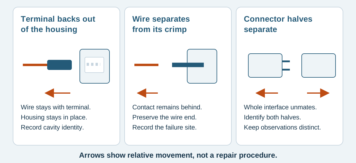
Conceptual illustration. It does not depict an approved product configuration or test result.
Identify the separation point
Use the housing, terminal and conductor as separate reference objects. Describe visible movement without forcing an uncertain diagnosis.
Scroll sideways to read all columns.
| Observation | Interface to investigate | Evidence to preserve |
|---|---|---|
| Wire and terminal have moved together relative to one cavity | Terminal retention inside the housing | Front and rear cavity views, terminal position and housing condition |
| Wire has separated while the terminal remains in the cavity | Wire termination, including the conductor crimp | Wire end, remaining terminal and any detached material |
| Housing and wires moved together away from the mating part | Retention between connector halves | Both mating parts, their engagement features and installed position |
| Electrical connection is intermittent but no displacement is visible | Fault location remains unresolved | Circuit identity, observed symptom and conditions when it occurs |
These events can coexist. A displaced terminal may be found after a connector was pulled apart, but that sequence does not establish when the displacement began.
The TPA and CPA guide explains assurance features. Here, the task is to record the failed condition. Do not assume that adding a secondary feature will resolve an unidentified separation mechanism.
Photograph the condition before changing it
Disconnect power and follow the equipment's isolation procedure before inspection. Photograph the installed cable route first, then the connector from the mating and wire-entry sides when those views can be obtained without disturbing the evidence. Include an assembly identifier and a scale where size matters.
Mark the affected cavity on a copy of the image. State whether numbering is viewed from the mating face or the wire side. “Second wire from the left” becomes ambiguous when an image is reversed or the connector is turned over. Use the approved drawing's cavity convention.
Keep an untouched specimen for supplier review where practical. Record every subsequent action: unmating, pushing a terminal forward, removing a cable tie or extracting a contact. Reinserting the terminal can erase useful positional evidence.
JST cautions against abnormal wire loading and describes how pulling only selected wires during removal can damage connections. Its handling guidance also warns against using nonmatching objects to check a connector's circuit because they can deform contacts. Use the selected part's specific instructions rather than improvising a probe or pull check. JST handling precautions, pages 3–5
Send a record that a supplier can investigate
The following fields form a practical issue record. Use “unknown” rather than filling gaps from a similar-looking connector.
Scroll sideways to read all columns.
| Record field | What to enter |
|---|---|
| Assembly identity | Part number, drawing revision, lot and unit identifier |
| Component identity | Proposed housing, contact and mating-part references; identify any unverified reference |
| Location | Connector designator, cavity number and labeled viewing direction |
| Observed separation | Which items moved relative to which reference surface |
| Discovery stage | Incoming inspection, equipment assembly, first mating, service or operation |
| History | Known mating cycles, earlier repair, transport damage and handling changes |
| Installation | Cable route, support points, access for gripping and visible tension |
| Evidence | Original image names, preserved specimen and test records |
| Population | Number observed and number actually examined in the identified lot |
| Changes after discovery | Each manipulation and who performed it |
Keep population wording precise. “Two displaced terminals in the eight units examined” is different from a defect rate established for an entire shipment. Identify how those eight units were selected.
Review candidates without assigning a cause from a photo
Possible review areas include incomplete insertion, damaged retention features, an incorrect terminal and housing combination, terminal deformation and load transmitted through the wire. Treat these as investigation questions until the component documents and specimen support a conclusion.
For one specific example, Molex's PicoBlade application specification separates terminal insertion from mating the completed connector. It identifies oversized crimp dimensions and incorrect insertion orientation as potential insertion problems. These instructions concern the constructions covered by document 510210000-AS; they are not universal dimensions or handling limits for every small connector. Molex PicoBlade application specification, sheets 16–18
Compare the actual proposed parts, wire and drawing revision with the supplier's build records. A family name or matching pitch does not prove that a replacement contact belongs in the original housing.
A fictional equipment assembly review
An assembler finds a rearward contact in J2 cavity 4 after routing a harness around an enclosure corner. The other cavities appear aligned. The connector had passed a stationary wiring check before installation.
A useful report says: “Contact and wire at J2-4 are rearward relative to adjacent cavities after routing. Initial installed photo retained. Terminal not reinserted. Cable route photo shows the support location.” It includes the preinstallation test reference and asks for review of insertion records and the installed load path.
It does not say “bad crimp” solely because a wire moved. Nor does the earlier continuity pass establish that terminal retention was adequate under the subsequent handling. The investigation must distinguish the condition at manufacture from what happened during installation.
Agree replacement and corrective action separately
Contain affected stock and agree inspection or return arrangements with the responsible supplier. Decide what evidence is needed before destructive examination. Replacement of the harness and correction of the underlying issue are separate release decisions.
Do not bend a retention feature back and presume its original performance remains. For the specified PicoBlade construction, Molex requires a new receptacle housing when repairing a previously inserted terminal because lifting the molded lance reduces its retention strength. Follow the exact product's disposition instructions. Molex specification, sheet 20
For custom discrete-wire cable assemblies, send the evidence record with the mating-part reference and drawing. Zeakka coordinates sourcing and supplier review as a trading partner; specialized failure analysis requires project confirmation. Original branded components within finished assemblies depend on exact part availability. A proposed unbranded compatible alternative needs its own validation and does not inherit the original's ratings or approvals.
Common questions
Does passing continuity rule out terminal backout?
No. The test describes electrical connections under its conditions. See the assembly testing guide for the distinction between wiring checks, crimp strength and terminal retention.
Can a clear photograph establish the root cause?
It can document displacement, damage or an apparent mismatch. Establishing cause may require the specimen, component specifications, process records and installation history.
Should I request stronger terminal retention immediately?
First identify the failed interface and application requirement. A change needs an agreed component configuration, test method and acceptance criterion; an unspecified request for “stronger” is difficult to verify.
Share this article
Help others discover this content