
Connector Datasheets, Drawings and Application Specifications
Table of Contents
A connector's series name is a starting point, not a complete build instruction. The catalog may explain the product family, while a drawing defines geometry and a separate application document controls wire preparation or termination. Buying a cable assembly requires those documents to agree with one identified construction.
Start with the full component references, then collect the documents that answer your actual questions. Do not choose whichever file is easiest to download and expect it to establish dimensions, processing and acceptance at once.
Read the right connector document
Match the document to the decision, then freeze the approved set.
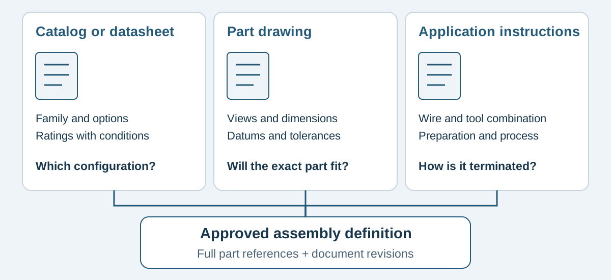
Conceptual illustration. It does not depict an approved product configuration or test result.
Match the question to the document
Use the following as a document-selection checklist. Manufacturers use different document names, so inspect the scope inside each file.
Scroll sideways to read all columns.
| Your question | Document to look for | Record before using it |
|---|---|---|
| Which family and configuration might fit? | Series catalog or datasheet | Exact variant and the conditions attached to ratings |
| Will this component fit the equipment? | Applicable component drawing | Part number, revision, views, datums and tolerances |
| Which parts form the intended connection? | Mating information and component tables | Housing, terminal and equipment-side references |
| How must the wire be prepared and terminated? | Product application instructions and tooling specification | Applicable terminal, wire and tool combination |
| What performance was specified or tested? | Product specification and applicable test requirements | Test conditions, component scope and acceptance criteria |
| What does this supplier have to deliver? | Approved assembly drawing, BOM and connection list | Assembly revision, supply scope and permitted changes |
A three-dimensional model can help check space, but a model is not a substitute for documented tolerances or processing requirements. Keep fit review and manufacturing release as separate decisions.
Follow one concrete component example
The public JST PH product page lists PHR-2, SPH-002T-P0.5S and B2B-PH-K-S as individual references. The PH catalog places these references in its housing, contact and header information. Use them to practice navigating the documentation for a two-position interface.
For the SPH-002T-P0.5S contact, the catalog lists AWG 30–24 and insulation outside diameter 0.8–1.5 mm. These are separate checks. A proposed wire described only as “26 AWG” still lacks its insulation diameter and full construction. The same catalog's tooling table identifies APLMK SPH002-05S for that contact. That reference identifies a tooling path to investigate; it does not supply every setup instruction.
The useful exercise is to build a record of the documents needed for this exact example. Do not convert the family name “PH” into permission to use any PH-shaped contact, wire or tool.
A worked document review
The following project is fictional. It illustrates a buyer's review record, not an approved JST assembly or a Zeakka order.
Example assembly A-104, revision A: two wires, each specified by the customer's wire code W-26-B; cable end PHR-2 with two SPH-002T-P0.5S contacts; B2B-PH-K-S is an equipment-side reference and is excluded from the supplied cable. The customer has not yet released the wire specification or processing documents.
Scroll sideways to read all columns.
| Review item | Information in the request | Decision needed before build release |
|---|---|---|
| Component identity | The three full references above | Confirm required suffixes and procurement identity |
| Wire suitability | W-26-B is described as 26 AWG | Obtain its construction and insulation diameter; check against the selected contact |
| Mechanical fit | Customer screenshot of the PCB area | Review applicable dimensions and the actual installed envelope |
| Termination process | No applicable process file identified | Confirm supplier tooling and the relevant instructions |
| Electrical definition | Two wires are shown without cavity numbers | Release a numbered connection list with a defined viewing direction |
| Inspection | “Check crimp” note | Agree characteristics, criteria, records and inspection stage |
The record prevents an apparently complete parts list from being mistaken for a released manufacturing package. A quotation can identify assumptions while those decisions remain open. A build release should resolve them.
Read drawing notes before measuring the picture
Check whether a view looks toward the mating face, the wire-entry face or the PCB mounting surface. Establish where circuit 1 is located in that view. Then check whether a dimension describes an unmated part, a mated assembly or a reference outline.
For your own assembly drawing, label the view explicitly. A mirrored cavity assignment can remain visually plausible in a clean drawing. Trace a named circuit through the view and connection list instead of relying on the page's left-to-right order.
Also separate nominal dimensions from toleranced requirements. A dimension copied into a customer drawing should keep its datum and applicable tolerance. Scaling a catalog illustration does not create a missing dimension.
Find processing requirements through the exact tooling reference
An application specification explains how a product is applied; a tooling specification identifies the relevant tool and its operating requirements. They may be separate files.
Molex's application-tooling guidance directs users to the specific tool's Application Tooling Specification, or ATS, for information including crimp height, pull force and strip length. The practical lesson for an RFQ is to request the applicable document reference rather than asking for an unexplained “standard crimp.”
For JST products, follow the applicable terminal and tooling instructions together with the general handling precautions. General precautions do not fill in a missing product-specific setting.
Resolve conflicting files before approving samples
Do not invent a universal rule that the newest download always overrides every other document. A later file can cover a different variant, tool or application.
When two files disagree, record the affected part, both document identifiers and revisions, the conflicting requirement, and the responsible decision owner. Ask the manufacturer or responsible design authority to resolve the discrepancy. Keep the written resolution with the assembly's released documents.
Freeze the approved set by document identifier and revision. A saved filename such as “connector-final.pdf” is difficult to audit when another file arrives with the same name.
Frequently asked questions
Is a series datasheet enough to request a quote?
It can begin a discussion. Identify missing details and quotation assumptions explicitly. The sample or production release needs a defined assembly, including its connection map and applicable processing requirements.
Can I copy the catalog current rating onto my cable drawing?
A component rating has defined conditions and scope. Establish the finished assembly's requirements using the selected wire, connections, installation and application review rather than converting a catalog number into an assembly guarantee.
What if a drawing is available only through the manufacturer?
Request the applicable file through the manufacturer's permitted process. Use the public catalog for preliminary discussion, and identify the unavailable detail as a release action.
For custom JST PH cable assemblies, send Zeakka the full component references and available documents. Zeakka coordinates sourcing and supplier review as a trading partner. Original branded parts are considered within finished assemblies, subject to the exact references and availability; alternative parts require their own documentation. Use the assembly drawing guide to connect the reviewed documents to the requested cable.
Share this article
Help others discover this content