
JST XH vs SH: What Changes When You Choose a Smaller Connector?
Table of Contents
JST XH uses 2.50 mm contact spacing; SH uses 1.00 mm. They are separate wire-to-board systems with different housings, contacts and headers. SH is not a smaller plug that can replace XH on the same board.
Quick choice: retain the matching series when the PCB interface is fixed. For a new design, assess SH for a compact connection using smaller wire; assess XH when its wire options and electrical ratings fit the requirement. Moving from XH to SH changes more than connector width: it requires a review of the wire, load, PCB footprint and assembly access.
XH vs SH comparison
The values below refer to original JST catalog components. They do not specify Zeakka's alternative samples or establish a finished cable's rating.
| Item | JST XH | JST SH |
|---|---|---|
| Standard contact pitch | 2.50 mm, not 2.54 mm | 1.00 mm |
| Catalog current | 3 A AC/DC with AWG 22 | 1 A AC/DC with AWG 28 |
| Catalog voltage | 250 V AC/DC | 50 V AC/DC |
| Catalog temperature | −25 to +85 °C | −25 to +85 °C |
| Contact example and wire limits | SXH-002T-P0.6: AWG 30–26, insulation OD 0.90–1.30 mm; SXH-001T-P0.6: AWG 28–22, OD 0.90–1.90 mm | SSH-003T-P0.2-H: AWG 32–28, OD 0.40–0.80 mm |
| Four-position housing example | XHP-4 | SHR-04V-S or SHR-04V-S-B, different variants |
| Board-side options shown | Through-hole top/side entry; SMT side entry also listed | SMT top/side entry |
| Structural distinction | Shrouded header; select the specified contact version | Housing lance retains the terminal; distinguish this from an external mating latch |
The temperature ranges include current-induced temperature rise. Contact options above are examples, not an exhaustive XH ordering list. Sources: JST XH catalog, pages 1–6 and 9; JST SH catalog, pages 1–4, checked 29 September 2026.
Identify the connector before comparing quotations
An equipment drawing or complete board-header part number is stronger evidence than a marketplace description. Record the housing, terminal and header separately. “Four-pin JST cable” leaves both the mating interface and the electrical pinout unresolved.
Measure contact-center spacing, not overall housing width. On a regular four-position row, the first-to-last centers span 7.50 mm for XH and 3.00 mm for SH. This calculation helps screen an unidentified sample; its mating geometry and drawing still need confirmation.
XH is also frequently confused with generic 2.54 mm products. Its nominal 2.50 mm pitch should remain 2.50 mm on the purchasing specification. Do not round it to an inch-based value or force a near-fitting connection.
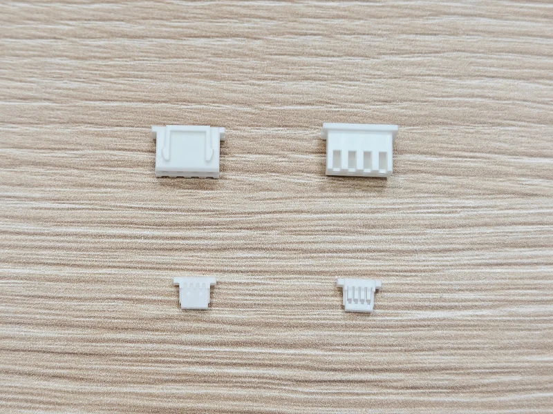
Alternative XH housings (top) and SH housings (bottom).
Browse XH-series alternative connectors and SH-series alternative connectors. Evaluate the exact alternative and its supplier documentation rather than treating visual resemblance as approval.
Downsizing from XH to SH: review the whole connection
The existing wire may not transfer
The listed XH contacts accept insulation diameters starting at 0.90 mm; the SH contact ends at 0.80 mm. Even where conductor gauges overlap, these listed insulation ranges do not. A proposal to keep the same wire while changing only the crimp terminal therefore needs more than an AWG check.
Record insulation OD as a controlled cable characteristic. If smaller wire is proposed, reassess conductor resistance, voltage drop, heating and mechanical handling for the actual cable length and load. Do not trim insulation to fit a terminal or infer approval from a successful continuity check.
A smaller interface is not an equivalent current path
XH's 3 A and SH's 1 A catalog values use different wire conditions. Neither is an unconditional rating for every contact, wire and installation. Review ambient temperature, simultaneously loaded circuits and duty cycle together with the selected components.
For an XH-to-SH cable connecting two different boards, the XH end does not raise the capability of the SH end. Specify the load for the complete path, including both connector systems and the wire. Likewise, XH's voltage figure cannot be assigned to an assembly containing SH.
Board and enclosure changes come together
SH's finer pitch reduces the contact-row span. Overall space savings depend on the chosen header orientation, housing dimensions and cable route. Include insertion travel, bend space and a practical way to grip the housing during disconnection.
Do not assume XH requires through-hole assembly in every case: the current catalog also lists SMT side-entry headers. Choose from the actual part drawings and available circuit counts. Changing between XH and SH still requires a PCB footprint and mating-part review.
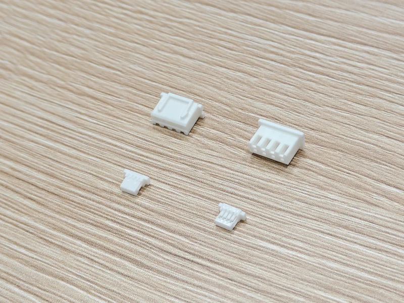
Angled view: alternative XH housings (upper row) and SH housings (lower row).
Contact selection affects service behavior
The XH catalog also lists SXH-001T-P0.6N as a lower-insertion-force option and notes reduced vibration resistance for that version. Similar-looking part numbers should not be consolidated into a generic “XH terminal” line on the bill of materials. Keep the approved reference intact.
For both series, distinguish terminal seating from completed mating. Use the applicable crimp inspection and retention criteria, and support the harness according to the installation. Housing size alone does not establish resistance to movement or repeated servicing.
What to include in an XH or SH RFQ
- Exact mating-header and housing references, terminal version, circuit count and original/alternative sourcing requirement.
- Pin-to-pin map with viewing direction and pin-one identification; wire colors alone are insufficient.
- Wire gauge, insulation OD and specification, finished length and tolerance.
- Requested end terminations or branches, plus separate protection, labeling and packaging requirements.
- Load and environmental conditions, inspection requirements, sample quantity and production quantity.
Zeakka offers alternative connectors. Finished cable projects can use original JST components sourced according to exact part selection and availability, or unbranded alternatives reviewed for the application. Original components are not sold separately. Specific SH cable configurations and requested original-part availability are reviewed per project.
Explore custom JST XH cable assemblies or send your XH/SH drawing for review. For a closer-pitch comparison, see JST PH vs XH; for compact interfaces, see JST GH vs SH.
Frequently asked questions
Can an SH cable replace an XH cable if the pin count matches?
No. Match both physical interfaces and the pin map. A change of series requires compatible board parts and a review of the complete assembly.
Is SH always preferable for signal connections?
No. Signal function alone does not settle wire fit, voltage requirements, mechanical access or the existing board interface. Choose against those constraints.
Can the XH 3 A rating be used for an XH-to-SH cable?
No. Assess the entire electrical path. The SH catalog's reference is 1 A with AWG 28; neither end's catalog value alone qualifies the finished cable.
Share this article
Help others discover this content