
How to Prepare a Cable Assembly Drawing
Table of Contents
A useful cable assembly drawing lets the buyer, assembler and reviewer identify the same build without guessing. It connects the component list, circuit map, physical dimensions and revision history. A neat outline alone cannot do that.
Start with the requirements you know and mark unresolved fields openly. A sketch can support an initial discussion, but a document containing unresolved connector references or circuit assignments should not be released as a manufacturing instruction. The cable assembly RFQ checklist covers the wider quotation package; this guide explains how the drawing itself fits together.
Start with one controlled example
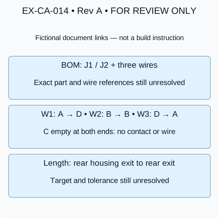
FOR REVIEW ONLY. Lettered cavities are placeholders, not official pin numbers; the incomplete example cannot authorize manufacturing.
The example below is fictional and incomplete: EX-CA-014, Revision A, FOR REVIEW ONLY. It describes three wires between two four-position housings. It is not a Zeakka product, customer drawing, connector specification or approved electrical design.
Give the drawing an assembly number, revision, date, sheet count and status. Use J1 and J2 consistently for the two ends. If the BOM or connection list lives in a separate file, record its identifier and revision on the drawing. Export a readable review PDF and retain the editable source under the same document-control process.
A reviewer should be able to answer: which files belong together, which version supersedes the previous one, and who can authorize release?
Identify both connector ends in the BOM
“Four-pin connector” or a family name is insufficient. Identify the exact manufacturer and housing reference, terminal reference, quantity and any secondary lock, seal or accessory. Record the equipment-side mating references separately, even when those parts are not supplied with the cable.
Scroll sideways to read all columns.
| Example item | Quantity | Required definition before release |
|---|---|---|
| J1 housing | 1 | Manufacturer and exact part number: TO BE CONFIRMED |
| J1 contacts | 3 | Exact part number and wire compatibility: TO BE CONFIRMED |
| J2 housing | 1 | Manufacturer and exact part number: TO BE CONFIRMED |
| J2 contacts | 3 | Exact part number and wire compatibility: TO BE CONFIRMED |
| W1, W2, W3 | 1 each | Wire specification, conductor size, insulation and color: TO BE CONFIRMED |
| Mating parts | Reference only | Exact equipment-side references and applicable drawings: TO BE CONFIRMED |
Do not assume the same terminal suits both ends. Conductor size and insulation diameter must fit each selected termination. JST's handling precautions direct users to confirm wire applicability for the chosen terminal and consult the relevant handling instructions.
If an alternative is allowed, identify its supplier and exact reference in a separate proposed BOM. “Or equivalent” must not conceal an unresolved substitution.
Connect the circuit table to explicit views
A circuit table describes connectivity; a connector view locates those circuits physically. Use both. Label each view as mating face or wire-entry side and show a recognizable key or latch. Verify the actual cavity numbering from the selected component drawing rather than assigning pin 1 from a photograph.
For example, the official JST GH catalog identifies circuit 1 in its component drawings. That information belongs to the parts and views shown there; it is not a universal numbering convention for other housings.
Our fictional map uses lettered placeholders specifically to avoid claiming official pin numbers:
Scroll sideways to read all columns.
| Wire | J1 placeholder cavity | J2 placeholder cavity | Identification |
|---|---|---|---|
| W1 | A | D | TO BE CONFIRMED |
| W2 | B | B | TO BE CONFIRMED |
| W3 | D | A | TO BE CONFIRMED |
| None | C | C | Intentionally empty at both ends; no contact or wire |
Before release, replace every placeholder with the verified cavity number and supply the corresponding views. Resolve wire specification and identification for each row. Color assists identification; it does not establish connectivity. Use the pinout and viewing-direction guide for a fuller orientation check.
Define what each length measures
State units and point to the exact reference surfaces. For this fictional review, choose the rear housing exit planes at J1 and J2 as length endpoints, then mark the target and tolerance TO BE CONFIRMED. State how the flexible assembly is positioned for measurement without stretching it. This is a document convention to review, not a recommended production dimension.
Keep cut-wire length separate from finished assembly length. If you add a branch, sleeve, label or heat-shrink section, give it its own location and extent. Show connector orientation and cable-exit direction where they affect installation. A tolerance should come from the fit requirement and agreed measurement method, not an arbitrary default.
Add notes that can be checked
Reference the agreed acceptance document and revision. Identify appearance, labeling, packaging or special evidence requirements where they affect this build. Avoid vague notes such as “high quality” or “fully tested.” The instruction needs an observable requirement, an agreed check and an acceptance criterion.
Do not copy a connector's catalog rating into an assembly-level guarantee. The selected wire, installation and application conditions still need review. Leave unresolved requirements visible in the issue list rather than embedding assumptions in the released drawing.
Close the loop before sampling
Walk through the package once as an independent reviewer: trace every connection, count contacts against populated cavities, check each end's BOM, and locate every dimension endpoint. Confirm the same revisions appear in the quotation, drawing and sample request.
If Revision B changes a connection, record the exact change and withdraw Revision A from active use. Keep the original revision available as history. When samples arrive, use the sample approval checklist to relate the actual build to the released documents.
Zeakka is a trading and sourcing partner. Send your drawing or marked sketch with its open questions so the project review can distinguish confirmed requirements from details that still need supplier and customer agreement.
Share this article
Help others discover this content