
Shrouded vs Unshrouded PCB Headers: Guidance, Protection and Access
Table of Contents
A shrouded PCB header surrounds its mating contacts with insulating walls. An unshrouded header leaves more of the pin field exposed. The useful purchasing question is which arrangement supports the equipment's connection, handling and service requirements within the available space.
Compare the same number of circuits and the complete mating system. A shroud can provide guidance or support a polarization feature, but its presence alone does not establish correct circuit assignment, positive locking, touch protection or environmental sealing. Those properties require evidence for the selected connector and assembled condition.
Compare the complete mating envelope at the same circuit count
Conceptual ten-circuit headers. These outlines are not manufacturer footprints or a universal keying arrangement.
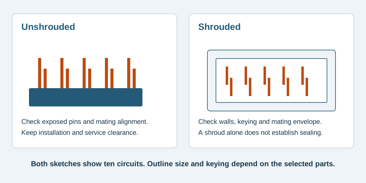
Conceptual illustration. Fictional examples are not approved product configurations, tooling instructions or inspection results.
Identify what the surrounding walls actually do
Inspect the mating path from the first approach through final engagement. Check which housing features encounter one another before the electrical contacts engage, and whether the operator can see or feel an incorrect approach without forcing the parts.
Scroll sideways to read all columns.
| Selection question | What to examine on the selected parts |
|---|---|
| Does the housing guide entry? | Wall, lead-in and mating-body geometry through the approach path |
| Is reversed mating prevented? | The actual asymmetric feature and its complementary mate |
| Is an offset connection prevented? | Whether the complete housing blocks a shifted or partial insertion |
| Are pins protected during handling? | Exposure before mating and access through the open end |
| Is the connection retained? | The specified latch, ejector, friction or other retention arrangement |
| Is water or dust excluded? | Documented sealing features and the applicable assembled-condition rating |
These are distinct checks. A surrounding wall can reduce some accidental contact with pins while leaving their tips accessible. A notch can accept the intended key without guaranteeing that every similarly sized socket has that key. Confirm the interaction rather than buying an assumed benefit from the word “shrouded.”
The polarization and keying guide addresses mismating prevention more broadly. For this decision, record the particular feature present on both proposed components.
Compare ten circuits with ten circuits
A documented dimensional example helps separate the contact grid from the plastic outline. Consider two original Samtec headers, each with ten contacts arranged as two rows of five at 2.54 mm pitch: unshrouded TSW-105-07-L-D and shrouded TST-105-01-G-D.
The table summarizes nominal or reference geometry for these examples. It is not a qualified substitution, a PCB land pattern or a complete tolerance drawing.
Scroll sideways to read all columns.
| Geometry item | TSW-105-07-L-D | TST-105-01-G-D |
|---|---|---|
| Contact arrangement | 2 × 5 | 2 × 5 |
| Along-row center span | 10.16 mm, calculated as four pitch intervals | 10.16 mm, calculated as four pitch intervals |
| Between-row center spacing | 2.54 mm | 2.54 mm |
| Header body length | 12.70 mm | 20.32 mm REF |
| Header body width | 5.08 mm | 9.27 mm REF, including the indicated outer features |
The TSW catalog, first page gives its straight-pin body geometry. The TST drawing, revision AQ, sheet 1 provides the reference outline and length formula: five positions per row × 2.54 mm + 7.62 mm = 20.32 mm.
The same contact count and center grid therefore occupy different header outlines. The example does not isolate the universal cost of adding a shroud: these are different series, with their own interfaces, dimensions and ordering options. Do not infer interchangeable footprints, mates or performance ratings from this table.
Add the mate and its movement to the outline
The header's plastic rectangle is only one part of the installed envelope. Add the specified mating connector, any cover or latch, cable exit where applicable and the space needed to connect and disconnect it.
For the named TST example, Samtec identifies IDC cable-assembly families among its mating options on the official product page. A board socket listed for another header is not automatically suitable simply because the pins appear to line up. Verify the exact proposed combination.
An enclosure opening may accommodate the unshrouded header body yet leave too little room for the selected socket to be gripped. A shroud may guide the plug but place a release feature beside a wall. Review the service motion in the actual board location, including the assembly order and what can be removed during repair.
Use the vertical versus right-angle guide for mating direction. Shrouded versus unshrouded is a separate selection dimension and does not decide that orientation.
Protect a bare pin field through the actual workflow
An unshrouded arrangement can be practical when the mating pair, alignment and handling are controlled. Decide how the board is stored, transported within assembly, installed and serviced before treating the exposed contacts as an acceptable detail.
For example, a fictional equipment layout EX-HDR-03 places a ten-contact header inside a removable cover. Its review identifies three stages: an unmated board on the assembly bench, initial socket placement and final enclosed operation. A cover fitted at the last stage does not protect the first two stages. The engineering team must assess handling protection and alignment at each one.
For a shrouded proposal, perform the same review. A bent pin, damaged wall or debris inside the opening may still obstruct mating. Do not prescribe a generic protective cap or an improvised straightening operation; any handling accessory and disposition method need approval for the actual parts.
Make the comparison a reviewable sourcing request
Provide both exact header and mating-part references, circuit count, pin assignment, board location and the required mating direction. Include the envelope of neighboring components, any cover opening and the service access requirement.
If an alternative component is proposed, request its own outline and recommended PCB layout. Check the full ordering code, material and finish, plus the evidence needed for the application. The original manufacturer's drawings and ratings do not qualify an unbranded replacement.
Identify whether the header is an item to be supplied or only the equipment-side mating reference for a finished cable assembly. This prevents a dimensional discussion from silently changing the purchasing scope.
Shroud selection questions
Does a shrouded header always prevent reverse mating?
Only the actual complementary geometry can establish that. Check the permitted mating part, polarization arrangement and drawing; a surrounding wall alone is insufficient.
Is a shrouded header waterproof?
The shroud does not establish a sealing rating. Use documented seals, assembly requirements and an applicable environmental rating if the equipment needs that property.
Can I reuse the existing PCB holes?
A similar contact grid is only a starting observation. Confirm hole dimensions, locating or retention features, body clearance and the exact footprint before approving a change.
Send the interface and access constraints together
For custom pin headers, send Zeakka the drawing, proposed mate, circuit mapping, quantity and available enclosure space. If a cable-side connection is included, identify its required exit and handling conditions. Zeakka is a trading and sourcing partner coordinating project review and supplier options. Original branded-component examples here explain engineering documentation; they are not an offer of loose original parts. Request a project review with the known references and unresolved constraints.
Share this article
Help others discover this content