
Vertical vs Right-Angle PCB Headers: Choosing Mating Direction and Cable Clearance
Table of Contents
A connector can fit inside an enclosure and still be impossible to plug in after the board is installed. The missing dimension is often the space needed to approach, mate, release and withdraw the cable connector—not simply the header's height.
Choose the mating direction from the assembly and service sequence. Then check the cable exit, installed cable route and board attachment separately. A right-angle header is not automatically the best solution for a low enclosure, and a vertical header does not guarantee easy access from above.
Define direction relative to the PCB
For the terminology used here, a vertical mating axis is perpendicular to the PCB surface; a right-angle mating axis is parallel to it. “Vertical” does not mean upward relative to gravity. A board installed upright still has its own reference plane.
Molex's general application specification distinguishes vertical, right-angle and top-entry configurations. Its illustrated top-entry type mates perpendicular to the board while the connected wires run parallel to the board. This is a useful reminder that mating direction and wire-exit direction are different characteristics. Confirm the terminology against the selected product drawing rather than treating the label alone as geometry. Molex 2166940000-AS, revision B, section 1-2, page 6
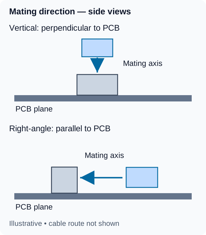
Conceptual side views only. Arrows identify the mating axis, not the cable route or a production assembly sequence. Shapes are not product drawings and are not to scale.
Compare the whole installation envelope
Header dimensions describe one component. The installed envelope also includes its mating connector, cable exit and any local protection. The temporary space needed during connection can be larger than the final occupied space.
Scroll sideways to read all columns.
| Question | Vertical mating axis | Right-angle mating axis |
|---|---|---|
| Where must the cable connector approach? | Along a path normal to the board surface. | Along a path parallel to the board surface. |
| What commonly blocks that approach? | A lid, another board or a structure above the interface. | An enclosure wall, adjacent component or blocked board edge. |
| Where must the release feature be reached? | Check the actual latch position and access around the cable connector. | Check whether the enclosure or cable route hides the actual latch. |
| What space remains after mating? | Measure the complete mated assembly and required cable route. | Measure projection along the board as well as total height and cable route. |
These are planning questions, not universal performance differences. Either orientation can require more useful installation space in a particular enclosure.
Do not compare an unmated header height on one datasheet with a mated height on another. Establish the drawing datum, the components included and the viewing direction. If a shield cover, sleeve or boot changes the cable-end outline, include that configuration in the envelope review.
Test the assembly sequence before selecting the smaller outline
Consider an illustrative enclosure with a removable top cover and little space beside the PCB. A vertical interface may allow the cable to be connected from above before the cover is fitted. A right-angle interface placed against the side wall could lack the approach space needed to insert or withdraw its mate.
Now consider a stacked-board arrangement with a clear side opening but restricted space above the connector. A side approach may be easier to access. That does not establish the required header automatically: the full connector projection, release access and cable route still have to fit.
For either arrangement, walk through the intended order: board installation, cable connection, fastening, cover installation and eventual disconnection. Identify which parts can actually be removed during service. If the only possible procedure requires removing the whole PCB, make that consequence visible to the equipment designer rather than discovering it during a repair.
Keep cable exit and cable bending on their own drawing
Draw the intended cable route from the connector exit to the first support or destination. A connector aligned with the available opening can still leave the cable needing an impractical turn immediately behind the housing.
Use the selected wire or cable's requirements and the connector application instructions to define that transition. Do not insert a universal clearance or bend-radius value simply because the connector is described as right-angle. A flat group of wires, a jacketed cable and a protected cable end can occupy different space.
Molex's general instructions warn against forcing the wire route so it loads the connector, and against extreme bending or stretching near the connection. Apply the detailed instructions for the actual assembly, rather than using the latch to hold a cable in a forced position. Molex 2166940000-AS, revision B, section 10-5, pages 33–34
The cable strain-relief guide explains the separate question of where mechanical loads are carried. This orientation decision establishes space and access; it does not prove strain-relief performance.
Orientation does not define the PCB mounting method
Vertical and right-angle describe the mating layout. Through-hole and surface-mount describe board termination arrangements. Specify both rather than using one as shorthand for the other.
For a concrete documentation example, the official Molex 43650 series chart identifies part 436500200 as a right-angle Micro-Fit header with through-hole mounting and a snap-in plastic peg PCB lock. Those are separate attributes of that part; another right-angle header need not use the same attachment features. The example identifies original-component fields, not the specifications of a Zeakka alternative. Molex 43650 series chart, part 436500200
Likewise, changing orientation is not a footprint-only substitution. Review the actual PCB layout, locating features, mating reference and any change to the connector's installed position. Preserve the pin mapping and the drawing's defined view; rotating a header illustration is not sufficient to establish electrical equivalence.
Turn the layout decision into a sourcing request
Provide the selected header reference or drawing, the cable-side mating reference and a simple enclosure section showing the PCB plane. Mark the intended insertion direction, the permitted mated envelope and the area that must remain accessible for release. State whether the board-mounted part is to be supplied or is only a mating reference for the cable assembly.
Existing Micro-Fit alternatives and JST GH alternatives are starting points for component review. Their catalog photographs do not establish every available orientation, footprint or exact mating combination. For a terminated harness, see custom Micro-Fit cable assemblies or custom JST GH cable assemblies.
Zeakka coordinates sourcing and supplier review as a trading partner. Request a project review with the layout constraints and exact references, so a proposed component set can be checked against the equipment's assembly and service access—not only against a connector family name.
Share this article
Help others discover this content