
Cable Assembly Test Fixtures: Mating Parts, Connection Maps and Wear
Table of Contents
A cable test fixture connects the assembly to the tester. Its mating parts, adapter wiring and point labels can affect the result, so the fixture needs an identity and a verification record alongside the assembly drawing and test program.
Before ordering a fixture, agree which product interfaces it must contact, how those contacts reach the tester and who maintains the resulting setup. “Use a matching connector” leaves several important decisions unresolved.
Trace each product endpoint through the fixture to the tester
Fictional EX-TF-33 mapping: J1 and J2 product endpoints connect through F1 and F2 fixture interfaces to four separate tester points. The product connection requirements and independent fixture verification remain separate records.
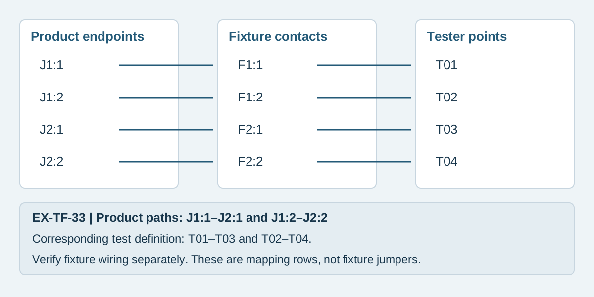
Conceptual illustration. Fictional examples are not approved product configurations, tooling instructions or inspection results.
Define the boundary of the fixture
Start with the assembly under test. List every connector, loose terminal, shield connection or other test-access point covered by the test plan. Mark anything intentionally outside the fixture's scope. Then define the adapter harnesses, replaceable mating interfaces and tester connections included in the fixture supply.
The equipment-side production connector and the fixture mating component are separate purchasing items. They may serve different handling and replacement needs. A fixture interface must nevertheless contact the correct product terminals without damaging the contacts, housing, latch or seal. A similar pitch or cavity count does not establish compatibility.
Record the exact mating component reference, contact arrangement, keying, engagement method and support required during connection. If a custom contact block is proposed, ask how it locates the assembly and reaches the intended surfaces. Do not approve an improvised probe solely because it produces a continuity indication.
Keep product endpoints separate from tester points
The pinout guide defines connector views and numbering. Keep those released identifiers in the fixture record. The tester may use a different point sequence; a mapping table connects the two systems without renumbering the product drawing.
EX-TF-33 is a fictional fixture for a two-circuit assembly EX-CA-33. J1 and J2 are product connectors. F1 and F2 are fixture interfaces. T01 through T04 are invented tester labels, not commands for a particular machine.
Scroll sideways to read all columns.
| Product endpoint | Fixture contact | Tester point | Required product connection |
|---|---|---|---|
| J1:1, drawing view A | F1:1 | T01 | J2:1 |
| J1:2, drawing view A | F1:2 | T02 | J2:2 |
| J2:1, drawing view B | F2:1 | T03 | J1:1 |
| J2:2, drawing view B | F2:2 | T04 | J1:2 |
For this fictional assembly, the intended product paths become T01–T03 and T02–T04 in the test definition. The mapping is not permission to join those points inside the fixture. Such a bypass could conceal a missing product connection. Confirm the fixture wiring independently of the assembly being evaluated.
Record unused positions too. A cavity deliberately outside electrical coverage is different from a tested point expected to remain isolated. Document the decision so an unconnected adapter wire cannot silently reduce the test scope.
Specify the input package before fixture manufacture
Scroll sideways to read all columns.
| Input | What the reviewer needs |
|---|---|
| Product baseline | Assembly reference, drawing revision and approved connection map |
| Mating interfaces | Complete component references, views, keying and any access restrictions |
| Test platform | Actual tester interface and relevant program format or naming convention |
| Electrical scope | Intended connections, isolation groups, shields and embedded components |
| Handling arrangement | How connectors are supported and engaged without loading product wires |
| Deliverables | Fixture drawing, point map, identification, verification evidence and maintenance instructions |
| Ownership | Who owns, stores, repairs and approves changes to the fixture and program |
Agree any additional electrical test separately. A fixture suitable for one continuity setup is not automatically suitable for a higher-voltage test. Required ratings, spacing, guarding and operating controls must be reviewed for that actual equipment and method. No test voltage is specified by this guide.
The testing overview explains what continuity, short-circuit and mechanical results cover. This fixture package explains how the assembly is connected to those agreed tests; it does not expand the purchased test scope.
Verify the fixture independently
Cirris describes fixture verification as a separate check of interface conductors, correct mating-pin connections and unwanted shorts. Its workflow illustrates why a product result depends on the interface as well as the product. The available verification features depend on the actual test system.
For a project, ask the responsible test engineer to define the verification method, reference, acceptance criteria and record. Include verification of the point labels against the released connector views. A known-good assembly alone may not expose every incorrect fixture connection or every excluded position; document the coverage of whichever reference is selected.
Keep the record tied to fixture ID and revision, program revision, date and reviewer. Initial acceptance, repair, changed wiring or a replacement mating interface should have defined return-to-use checks. The plan should also state what happens if an in-use fixture fails verification, including review of product results potentially affected since the last acceptable check.
Make wear parts and replacement responsibilities visible
The Cirris adapter guidance notes that mating interfaces wear with use and that contact resistance can increase. Its replaceable-adapter approach is one manufacturer's implementation, not a claim that every supplier uses that system.
Identify the replaceable item in the fixture BOM and record the permitted replacement reference. Set inspection or verification intervals using the chosen component guidance, use conditions and agreed maintenance plan. Do not copy a generic mating-cycle number into every fixture specification.
A replacement that changes wiring, contact arrangement or measurement contribution needs appropriate review. Keep the removed part, symptom and action traceable when investigating disputed results. Repeatedly reconnecting until a unit passes is not a substitute for identifying an unreliable interface.
Frequently asked questions
Does a passing cable prove the fixture is correct?
No. It is one result from that combined setup. Verify the fixture mapping and condition using the agreed independent method and retain its record.
Must every project use the same test equipment?
No. Define the required checks and evidence first, then confirm the actual equipment and interfaces. A tester-specific adapter or software feature should not become an assumed universal requirement.
Who pays for replacing a worn fixture connector?
Agree this commercially before manufacture. Record ownership, spare-part scope, maintenance responsibility, replacement approval and any effect on delivery timing.
Send the interface package with the RFQ
For custom cable assemblies, send the released connection map, mating-interface details and requested test records. Mark fixture ownership and maintenance questions explicitly. Zeakka coordinates sourcing and supplier review as a trading partner; the proposed fixture, platform and evidence require project-specific confirmation. Contact Zeakka to include those decisions in the quotation.
Share this article
Help others discover this content