
Choosing Wire Gauge for Cable Assemblies: AWG, Voltage Drop and Connector Limits
Table of Contents
Choosing wire gauge is a circuit decision, not a lookup of one current against one AWG number. A usable assembly must deliver enough voltage at the equipment, stay within its electrical and thermal limits, fit the exact terminals and insulation supports, and work in the installed space. Passing one of those checks does not settle the others.
This guide focuses on low-voltage copper power wiring in equipment. It is not an installation-code ampacity table or a signal-integrity design guide. For connector-specific wire ranges, use the JST wire gauge and current-rating guide alongside the exact component drawings.
Start with the load and the complete current path
Record the supply voltage range and the lowest voltage the equipment can accept at its terminals. Identify steady operating current, startup or stall current where relevant, pulse duration and repetition, and which circuits operate together. A motor starting briefly and a heater running continuously should not be reduced to the same average-current entry.
Draw both the outgoing and return paths. For a dedicated two-wire DC circuit with equal conductor lengths, the resistance calculation normally includes both wires. A shared return, chassis return or branched harness needs its actual network drawn; do not automatically double one length or assume that each branch has an independent return.
Scroll sideways to read all columns.
| Decision input | Why it matters | What to provide |
|---|---|---|
| Load current and time profile | Voltage loss and heating depend on operating conditions | Continuous current and relevant transient conditions |
| Outgoing and return routes | Both contribute to the complete circuit | Electrical path lengths, branches and common sections |
| Available voltage margin | The load must receive enough voltage | Supply tolerance and equipment minimum voltage |
| Installation | Heat rejection and routing vary | Ambient range, bundles, enclosure and nearby heat sources |
| Termination | Wire must suit the exact contact and insulation support | Connector, terminal and wire part numbers |
Use the selected wire's resistance, not its jacket diameter
AWG describes conductor size; a lower AWG number generally denotes a larger conductor. It does not state the insulation thickness, finished wire outside diameter or permitted current for every installation. Two wires with similar outside diameters may contain different amounts of copper.
Obtain the proposed wire's conductor material, size, strand construction and DC resistance data, including the reference temperature and whether the value is nominal or a maximum. Keep units consistent: ohms per metre and ohms per kilometre are not interchangeable without conversion. For a conservative design check, use the applicable specified limit and operating-temperature basis rather than silently treating a nominal room-temperature figure as guaranteed.
Manufacturer data separates these properties. For example, the Belden 8503 product specification identifies conductor construction and electrical characteristics separately from cable dimensions and temperature information. It is a reference example of the information to request, not a recommendation for every Zeakka assembly.
Copper resistance increases as conductor temperature rises. Evaluate resistance at the relevant conductor temperature, which can differ from ambient after self-heating. If the proposed data does not provide the needed basis, have the wire supplier and equipment designer resolve it before fixing the gauge.
Calculate a defined DC voltage-drop case
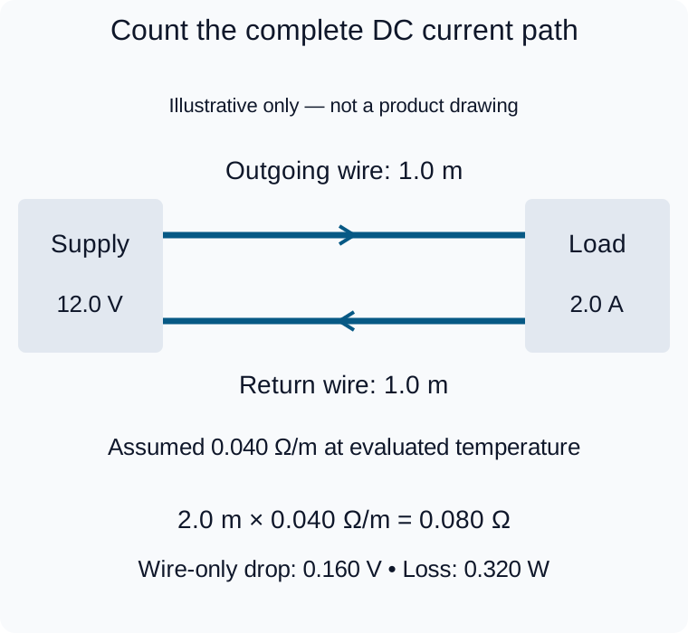
Illustrative calculation only. Both conductors contribute resistance; contacts and splices are omitted and thermal suitability remains a separate check.
For a simple series DC path, voltage drop is current multiplied by total path resistance. Add wire, connector-contact, splice and other relevant series contributions on a consistent basis. Avoid counting the same contact twice if an assembly resistance measurement already includes it.
Consider this illustrative calculation only, with assumed values rather than a rating for an AWG size or supplied product:
- Supply at the chosen operating condition: 12.0 V.
- Constant load current for this calculation: 2.0 A.
- Copper outgoing wire: 1.0 m; copper return wire: 1.0 m.
- Assumed wire resistance at the evaluated temperature: 0.040 ohm per metre.
- Contacts and splices omitted initially, then assessed separately.
The wire loop is 2.0 m, so its resistance is 0.080 ohm. Wire-only drop is 2.0 A × 0.080 ohm = 0.160 V. The calculated load voltage is 11.84 V before the omitted connections. Wire-only dissipation is 2.0² × 0.080 = 0.320 W, distributed along the two conductors.
Doubling both wire lengths doubles this wire-only drop at the same current and temperature basis. It does not double the connector rating or demonstrate an acceptable final temperature. If the equipment's voltage margin is smaller than the total predicted loss, revise the circuit or cable selection. Repeat the check for the limiting supply and load conditions; do not turn this example into a universal allowable percentage.
Check thermal suitability independently
A short cable can have a small voltage drop yet still run too hot at a terminal or inside a tightly packed bundle. Conversely, a thermally suitable wire on a long run may lose too much voltage. Insulation temperature marking alone does not specify a safe current for the finished harness.
Review the installed ambient, simultaneous loaded conductors, duty cycle, enclosure, bundling and nearby heat sources with the responsible designer and supplier. Do not reduce a repetitive pulse case to an arithmetic average without checking its actual heating and transient requirements. Temperature rise or application qualification may be needed; agree that scope rather than assuming routine continuity testing establishes it.
Treat the terminal as a separate selection constraint
A larger conductor is not an automatic upgrade if its strands or insulation no longer fit the approved terminal and crimp setup. Check the exact terminal variant, conductor range, insulation diameter, strip length and applicable tooling instructions. Never remove strands to make an oversized wire fit.
Connector current ratings also depend on stated conditions. Molex's Mini-Fit TPA specification, sections 4.2–4.4 distinguishes applicable wires and describes current-rating conditions involving circuit count, temperature rise and application factors. Those original-component conditions do not automatically rate a compatible alternative or a completed assembly.
If the required wire is outside the contact range, review a suitable connector/contact combination or a separately engineered transition. Do not assume parallel contacts divide current equally or increase the allowable current by simple multiplication.
Request a matched wire-and-termination proposal
For custom cable assemblies, send the circuit conditions and installed route together with the desired connector configuration. Ask the proposal to identify the actual wire construction and resistance basis, exact terminal compatibility, and which voltage-drop or temperature assumptions still need confirmation.
Zeakka coordinates sourcing and project review with suppliers; this is not a promise of a standard current rating or thermal qualification for every build. Contact Zeakka with the application inputs. Use the cable testing guide to distinguish routine electrical checks from additional validation that your design may require.
Share this article
Help others discover this content