
Solid vs Stranded Wire for Cable Assemblies
Table of Contents
Solid wire uses one metal conductor. Stranded wire uses several smaller strands to form a conductor. For cable assembly buyers, the useful question is which construction fits the installed route, expected movement, and exact termination. Neither is a universal upgrade over the other.
Stranded wire is generally easier to route where flexibility matters. Solid wire can suit fixed connections when the wire and terminal specifications allow it. Before accepting either construction, check the selected wire part number against the assembly's mechanical, electrical, and termination requirements.
What changes inside the wire?
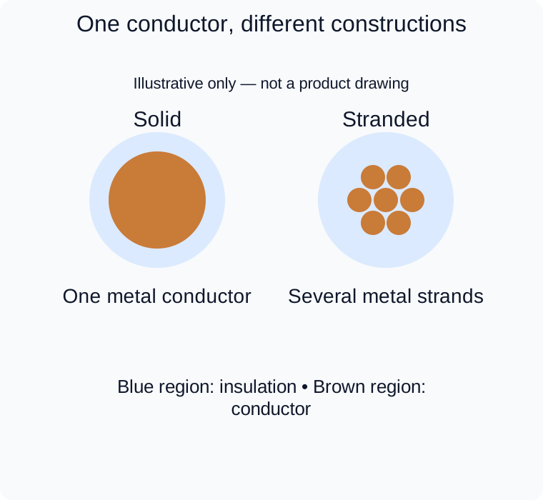
Conceptual sections only, not equal-area or exact strand-count specifications. Neither sketch demonstrates continuous-flex capability.
The distinction concerns the metal inside each insulated wire, not the number of circuits in the cable. A cable containing four insulated wires can use solid conductors or stranded conductors. A stranded conductor still forms one electrical path; its individual strands are not separate circuits.
Belden's explanation of solid and stranded conductors describes the single-piece and multiple-strand constructions and their different flexibility characteristics. Its networking examples should not be treated as universal electrical limits for other cable assemblies.
For procurement, record the conductor construction alongside its size and material. A description such as “stranded copper” leaves important details open. The wire specification may also identify strand count, individual strand diameter, plating, insulation material, and finished outside diameter. These details help distinguish wires that share the same nominal gauge but are not interchangeable in an assembly.
Start with the movement the assembly will experience
Separate bending during installation from movement throughout the equipment's life.
Scroll sideways to read all columns.
| Application condition | Selection direction | What to confirm |
|---|---|---|
| Fixed route after installation | Solid or stranded may be suitable | Routing space, wire bend limits, and terminal compatibility |
| Occasional repositioning or service access | Consider a suitable stranded construction | Actual movement, available slack, and the wire or cable's stated use |
| Repeated bending in a moving mechanism | Select a cable designed for the required motion | Dynamic bend radius, motion type, and supporting life data |
| Twisting with robot or rotary motion | Assess torsion suitability separately | Permitted twist, travel, mounting, and operating conditions |
“Stranded” does not mean “continuous flex.” A wire that feels soft in the hand has not thereby demonstrated a specified service life in a moving machine. igus's continuous-flex design guidance explains that strand diameter, pitch, and direction work together with insulation, core arrangement, shielding, and jacket design.
For a moving application, describe where the bend occurs and how often it repeats. Ask for product-specific motion data under conditions relevant to your installation; do not transfer a cycle claim from another cable. Also review the connector exit and support arrangement. Our cable assembly strain relief guide covers that separate part of the design.
The termination must accept the selected construction
A wire's fit inside a terminal is not proof that the connection is approved. Use the terminal manufacturer's drawing and application specification to check conductor type, permitted wire size, insulation diameter, preparation, and tooling.
Crimp connections: Do not assume every crimp contact accepts both constructions, or that solid wire can never be crimped. As a specific counterexample, TE Connectivity's SOLISTRAND splice 134540-1 lists compatibility with both solid and stranded copper wire. That approval belongs to the selected product and its documentation; it does not extend to an unrelated miniature connector contact.
IDC connections: Insulation displacement is also product-specific. TE's IDC Poke-In connector series includes designs for solid and stranded leads. This does not make every IDC terminal suitable for every stranded wire. Confirm the exact part's conductor and insulation requirements before changing the wire construction.
Terminal blocks and prepared ends: Follow the selected terminal's instructions for direct insertion, ferrules, or other end preparation. Do not add a ferrule simply to make a wire appear compatible; the resulting termination must be supported by the terminal specification.
If a proposed replacement keeps the same gauge but changes stranding or insulation, treat it as a compatibility review, not an automatic substitution.
Gauge alone does not complete the specification
AWG or nominal cross-sectional area is only one selection field. Check the wire's finished diameter against seals, insulation support features, routing openings, and other constrained interfaces. Check the conductor and insulation requirements separately: a nominal gauge match cannot resolve an insulation diameter mismatch.
Keep electrical selection tied to the actual application. Obtain the wire's resistance and rating data, then assess operating current, circuit length, temperature, and installation conditions alongside the connector limits. The words “solid” and “stranded” alone do not establish a safe current rating or an acceptable voltage drop.
For example, Belden 9976 identifies its solid conductor construction separately from its insulation diameter, voltage rating, temperature rating, and bend radius. Use the same level of product-specific detail when comparing candidate wires; those published values apply to that wire, not to all solid wire.
What to send for a useful selection review
For this decision, the most useful starting information is:
- The approved wire part number, or the required size, material, plating, and conductor construction.
- The contact or terminal part number at each end, including relevant application specifications.
- A route sketch showing confined bends, supports, service movement, or continuous motion.
- Operating current, circuit length, temperature, and environmental requirements that affect the choice.
- Any proposed substitution, with the changed construction or dimensions clearly identified.
Zeakka works as a sourcing partner for cable assembly projects. Send the wire and termination requirements for project review to discuss a potential supply option. Wire availability, termination suitability, and any requested supporting evidence need confirmation for the specific project.
Share this article
Help others discover this content