
Shielded Cable Assemblies: Foil, Braid and Shield Termination
Table of Contents
A shielded cable assembly needs more than a cable marked “shielded.” The cable construction, connector interface and connection to the equipment must support the intended shielding arrangement. Two assemblies using the same bulk cable can differ substantially at their ends.
For a purchasing review, separate three decisions: what surrounds the conductors, how that screen is terminated, and where the equipment design connects it. This guide helps identify those decisions before a sample or quotation is approved.
Foil, braid and drain wire have different jobs
Scroll sideways to read all columns.
| Element | What it contributes | What to clarify |
|---|---|---|
| Foil shield | A thin conductive layer around a core or individual group | Material, overlap, conductive face and specified termination |
| Braided shield | Interwoven conductive strands surrounding the cable core | Material, coverage and compatibility with the selected termination |
| Foil plus braid | Both shield constructions within one cable | Layer arrangement and how the termination contacts them |
| Drain wire | A conductor contacting a shield to facilitate its connection | Size, contact arrangement, insulation and endpoint |
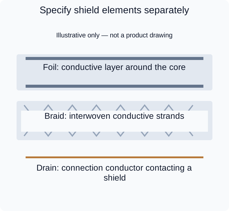
Separate shield concepts, not a complete cable drawing or a recommended grounding arrangement.
A drain wire is not a substitute for a surrounding shield. Nor does the presence of braid mean the cable has continuous metal coverage: there are openings between its strands. Foil and braid can be combined rather than treated as mutually exclusive choices. See Belden's explanation of shielding constructions and its shielding technical information.
Specify whether shielding surrounds the whole cable, individual pairs or both. A drawing that only says “shielded” leaves that distinction unresolved. Ask for the exact cable construction and part reference; an attractive cutaway photograph cannot establish the build being quoted.
Coverage is not a performance guarantee
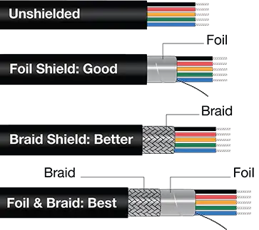
Reference diagram with English labels, not a photograph of a Zeakka product. Its “Good,” “Better” and “Best” labels are qualitative illustrations, not a universal ranking or an assembly performance rating. Actual shielding depends on interference frequency, cable construction, termination and the equipment system.
A foil specification describing full coverage does not mean the finished assembly blocks all interference. Likewise, a braid coverage percentage is a construction characteristic, not an attenuation rating for the completed cable.
Review the interference frequencies, cable routing, connector interfaces and equipment arrangement together. Keep the source of a requirement clear: is shielding specified by the equipment manufacturer, inherited from an existing approved assembly, or proposed to address a measured problem? These starting points require different evidence before a substitution can be accepted.
If motion is involved, request the selected cable's applicable bend and flex information. Do not assign a flex life from the words “braided shield,” or assume a cable suitable for installation bends is suitable for continuous movement. A shield construction alone is not a complete cable specification.
Termination completes the shielding arrangement
Shield termination is the physical and electrical transition from the cable screen to a specified contact, shell, clamp or enclosure. It deserves its own drawing detail.
A pigtail is a wire connection from the shield to a termination point. A circumferential connection instead contacts the shield around the cable through a suitable termination arrangement. Analog Devices explains why pigtail connections can present excessive impedance at high frequencies and why connector-to-enclosure continuity matters. A continuity reading alone cannot describe that high-frequency behavior. See Analog Devices, Hardware Design Techniques, section 8, page 8.84.
For review, show where the jacket ends, how much shield is exposed, how the shield is captured and where the insulated conductors continue. Identify the actual connector shell or contact involved. If a drain wire is used, show its finished length and insulation treatment. Do not let an assembler choose an unspecified endpoint simply because a nearby terminal is labeled “ground.”
A connector with signal contacts does not necessarily offer a shield termination. Confirm the complete mating interface and the equipment-side connection before approving the cable-side detail.
Keep shield, signal return and protective earth distinct
Do not automatically assign a shield or drain wire as the signal return. The circuit design must define the return path; some cable architectures intentionally combine functions, but that cannot be assumed for a custom multiconductor assembly.
Protective earth is a separate safety requirement. A screen connection does not automatically qualify as a protective conductor. For example, Schneider Electric's ATV212 instructions explicitly retain the requirement for PE conductors alongside the cable shielding arrangement. That is an equipment-specific example, not a wiring instruction for another system. See the ATV212 installation manual, EMC section.
There is also no universal instruction here to connect every shield at one end or at both ends. The responsible system designer must specify the arrangement using the equipment requirements, interference environment and grounding design. Record each end separately, including any required isolation. “Ground shield” is too ambiguous to release as a manufacturing instruction.
Review the transition as an assembly detail
Shield contact and mechanical restraint may sit close together, but they require separate assessment. Show which feature carries pulling loads and which makes the electrical connection. The cable assembly strain-relief guide covers the mechanical decision in more detail.
For a branch, splice or connector change, show what happens to every relevant shield at that transition. Identify where an overall screen stops and how any separately screened branches are handled. These details should remain visible in the controlled specification even when the finished covering hides them.
Make the review package specific to shielding
Send an annotated assembly drawing with these items:
- The cable reference and required overall or individual shielding.
- A termination detail for each end and any branch or splice.
- The specified shield endpoints, isolated points and separate signal-return or PE connections.
- The mating connector and enclosure arrangement, with routing or motion constraints.
- The required acceptance evidence and who owns equipment-level EMC validation.
Construction inspection, electrical connection checks and EMC evaluation answer different questions. Agree any shield-specific verification separately; the cable assembly testing guide explains the limits of routine wiring checks.
Zeakka is a trading and sourcing partner. We coordinate specification clarification and supplier review; the feasibility of a particular shielded construction, termination process and validation requirement needs confirmation for each project. This guide does not establish a Zeakka EMC or RF performance rating or test capability. Send your shield termination drawing for review, including any unresolved connection details.
Share this article
Help others discover this content