
Connector Current Ratings Explained: Wire Size, Circuit Loading and Temperature Rise
Table of Contents
A connector's headline current rating is a starting point for selection. The usable current in an assembly depends on the exact contacts, wire and mating parts, the circuits carrying load, and the temperature around the connection. A family described as handling a particular current does not automatically give every cable using that name the same rating.
This guide explains how to read connector current data. For conductor resistance and voltage-drop calculations, use the wire-gauge selection guide.
Identify what the rating actually describes
Start with the selected housing, terminal and mating header or plug part numbers. Then find the applicable product specification and its revision. A housing drawing establishes mechanical details; it may not establish the electrical performance of the assembled contact pair.
Read the rating together with its conditions. Record these beside the proposed assembly drawing so the number does not become separated from its basis during purchasing:
Scroll sideways to read all columns.
| Specification input | What to check |
|---|---|
| Contact configuration | Terminal variant, contact material, plating and approved mating part |
| Wire | Conductor size and construction, insulation diameter and terminal compatibility |
| Circuit configuration | Connector size, positions populated and simultaneous loaded positions |
| Thermal basis | Ambient temperature, permitted rise and applicable temperature limits |
| Installation | Cable routing, enclosure, airflow, nearby heat sources and PCB connection |
If the catalog summary and detailed specification appear inconsistent, resolve the exact-part scope with the manufacturer before approving the selection. Choosing whichever number is larger leaves the important question unanswered.
Read across the table, not just down the largest-current column
Molex's Mini-Fit Jr. specification provides a useful example. In revision H2, section 4.3, the brass-contact table lists 9 A for 16 AWG in the 2–3-circuit column and 6 A in the 12–24-circuit column. These are original-component guidelines based on a maximum 30°C rise over ambient, with application-dependent derating. They are not universal Mini-Fit or completed-harness ratings. Molex PS-5556-001, section 4.3
The practical lesson is to preserve every relevant table heading. A copied value without its wire size, contact material and circuit-size column cannot support an assembly decision. Nor should a table organized by connector circuit size be silently reinterpreted as a table covering any arbitrary pattern of loaded contacts.
Ask for the manufacturer's loading arrangement when it is not clear. Your design review should identify the actual positions carrying current simultaneously, including return paths and any common connection carrying several branch loads.
Separate ambient temperature from temperature rise
Ambient temperature is the local thermal environment around the connector. Temperature rise describes how much hotter the measured location becomes relative to that ambient under the stated test conditions. The equipment room temperature may differ from the ambient inside a closed enclosure.
For illustration only, a measured 25°C rise above a local ambient of 45°C gives a measured-location temperature of 70°C. This arithmetic does not predict a connector's rise at another current or prove that 70°C is acceptable. The relevant component and application limits still need checking.
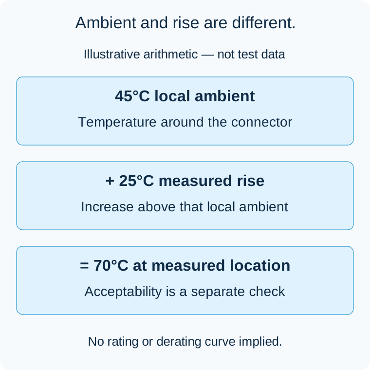
Illustrative arithmetic, not test data or an acceptable operating-temperature limit. The measured location and applicable limits must be defined separately.
Samtec describes current-carrying-capacity testing against temperature rise and publishes data for different contact configurations. Its stated derating approach belongs to that test basis; it should not become a default percentage for another manufacturer's connector. Samtec current-rating explanation
When reading a derating curve, check both axes, the applicable configuration and the treatment of ambient temperature. Determine whether the curve already includes a design margin. Do not apply a second margin by accident, or remove the published one merely because a prototype feels cool.
Wire size matters, but it does not settle the rating
A larger conductor can change resistance and heat transfer, but it must fit the selected terminal and its approved termination process. Substituting thicker wire does not authorize the highest current shown elsewhere in the connector family.
For an assembly proposal, request the actual wire and terminal combination. If the required conductor falls outside the terminal's range, revisit the interface or an engineered transition. Do not trim strands to make the wire fit. Keep wire selection and connector selection linked while treating voltage drop as a separate acceptance question.
Likewise, multiplying a per-contact rating by the number of positions does not establish allowable connector current. Several loaded positions share the surrounding thermal environment, and parallel paths should not be assumed to divide current equally.
Compare the installed case with the published case
Build a short application record: continuous current per position, relevant startup or pulse behavior, simultaneously active circuits, local ambient range and installation arrangement. Mark which assumptions match the manufacturer's data and which remain open.
A bench sample outside the enclosure may answer a different question from the finished equipment. If a thermal assessment is required, agree the assembly configuration, loading, measurement locations, stabilization criterion and acceptance limits with the responsible engineering team before testing. Routine wiring checks do not establish a thermal rating; the cable testing guide explains that distinction.
Request a proposal with a traceable rating basis
For custom Mini-Fit Jr. cable assemblies, send the exact interface references and the application record with the drawing. Ask the proposal to identify the selected components, the supporting rating conditions and any additional validation required.
Zeakka coordinates sourcing and supplier review as a trading partner. Original branded components are considered within finished cable assemblies, not as a standalone component offer. A compatible alternative needs evidence for its own proposed configuration; an original manufacturer's rating does not transfer through physical resemblance. Contact Zeakka to review the assembly requirements and unresolved conditions before quotation approval.
Related selection guides
Molex Mini-Fit Jr. vs Mega-Fit: Choosing a Power Cable Interface · Tin vs Gold-Plated Connector Contacts: How to Choose
Share this article
Help others discover this content