
Connector Housings, Terminals and Headers Explained
Table of Contents
A request for a “six-pin connector” can mean an empty housing, a set of metal contacts, a PCB-mounted header or a complete terminated cable end. Those are different purchasing items. Identifying which one is required prevents a quotation from including the right-looking plastic part while omitting the components that make the connection work.
For a cable assembly, define both sides of the interface and the components fitted to each side. A housing part number is an important starting point, but it is rarely the complete specification for a crimp-style cable end.
Three component names, three different jobs
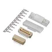
GH alternative catalog component group: separate contacts, cable housings and board-side connectors. This group is not an approved BOM or proof that every part pictured mates with every other part. View GH alternatives.
Scroll sideways to read all columns.
| Component | Main role | What its reference does not settle by itself |
|---|---|---|
| Housing | Insulates and positions contacts; provides the system's specified mating and retention features | Exact wire-compatible contact, populated cavities and electrical pin assignment |
| Terminal or contact | Makes the conductive interface and connects to the wire or another termination | Correct housing, approved mate and complete assembly rating |
| PCB header | Provides the board-mounted mating interface, with contacts and a board termination arrangement | Cable-side contact choice, cable pinout and clearance around the installed assembly |
“Terminal” and “contact” are sometimes used differently in manufacturer catalogs. Follow the selected system's names rather than assuming a universal naming convention. In this guide, a crimp terminal means the separate metal component terminated to a wire and inserted into the specified housing.
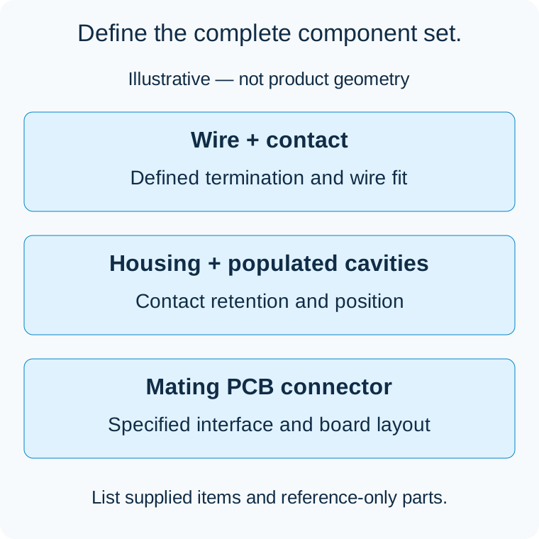
Illustrative component relationship, not a product drawing, approved mating combination or insertion sequence. Some connector constructions integrate parts differently.
A housing organizes contacts; it is not the whole cable connector
The housing defines cavity positions and the mechanical interface, including the applicable latch, polarization and mounting arrangement. Its circuit count describes available positions, not necessarily the number of wires fitted in your cable.
A six-position housing may have fewer populated cavities if the design requires that arrangement. The drawing must identify which positions are fitted and what happens at the unused ones. Do not substitute a smaller housing simply because the cable uses fewer wires; it may no longer fit the equipment-side connector.
Also distinguish an empty cavity from a blocked cavity used as a mechanical feature. Neither should be invented by the assembler to solve an unclear parts list. Use the specified components and cavity map.
A terminal must fit both the housing and the wire
The metal contact has a mating end and a wire-termination end. A contact that accepts the intended conductor is not automatically suitable for the housing, and a contact that enters a cavity is not automatically an approved replacement.
JST's GH catalog gives a useful concrete warning. It specifies SSHL-002T-P0.2 for GH and explicitly says that SSHL-003( )-P0.2 cannot be used with GH connectors. The similar-looking reference is not permission to interchange the parts. The catalog also separates conductor size from insulation outside diameter when defining the applicable wire. JST GH catalog, contact section, page 2
Record the full contact reference, approved wire construction and size, insulation diameter, and applicable termination requirements. Preserve suffixes that distinguish a material, finish or other functional option. Packaging variants may also affect procurement; resolve their equivalence through manufacturer documentation rather than deleting digits from a part number.
For an alternative contact, request its own documented housing and wire compatibility. Original-component tooling or crimp settings should not be assumed suitable merely because the replacement resembles it. The alternative-connector verification guide explains the evidence needed beyond visual fit.
A header brings the interface onto the PCB
A PCB connector combines an electrical mating interface with a board attachment and termination arrangement. Check the exact footprint, contact orientation, mounting surface and required assembly clearance. Top-entry and side-entry versions can lead the cable in different directions even when the cable housing belongs to the same system.
JST's GH catalog illustrates separate top-entry and side-entry layouts and identifies the viewing direction for its PCB layout. Those drawings are specific to the illustrated components; rotating a photograph is not a substitute for selecting the correct board part. JST GH catalog, PCB and assembly layouts, pages 2–3
For an existing product, the header may already be fixed by the PCB design. In that case, treat its exact reference as a constraint on cable selection. State whether it is supplied only as a mating reference or is also an item you want quoted. That distinction avoids accidentally adding board parts to a cable-only order.
Do not assign contact gender from the plastic shape
Pin and socket describe the conductive mating interface. Plug and receptacle describe housing or connector forms under the manufacturer's terminology. The two classifications do not always line up: a plug housing can contain socket contacts, and PCB headers are not invariably pin contacts. Molex explicitly distinguishes these terms and shows receptacle-style headers as well as pin headers. Molex connector mating fundamentals
Use the full part references and drawings instead of ordering by “male plastic” or “female shell.” Likewise, the side carrying pins does not by itself define power direction, signal function or safe exposure. Those are equipment design decisions.
Turn the component set into a clear assembly request
For each cable end, list the housing, contact reference and contact quantity. Add the mating connector as a separate reference, then identify the wire and cavity assignment. Include any required seal, retainer or other accessory only when it belongs to the selected system and configuration.
An illustrative four-position cable end might require one housing, three populated contacts and one specified unused cavity, while its PCB mate is reference-only. That describes the purchasing structure; it is not a production-ready BOM or a claim that any arbitrary three contacts fit a four-position housing. Component compatibility still comes from the applicable documents.
Use the cable assembly drawing guide to connect that BOM with the defined mating-face view, pin mapping and revision. This keeps the parts list and the required wiring tied to the same approved design.
For custom JST GH cable assemblies, send the existing mating reference even if the cable-side parts have not yet been selected. Zeakka coordinates sourcing and supplier review as a trading partner. Original branded components are considered within finished cable assemblies, not loose-component sales; proposed alternatives need their own supporting evidence. Contact Zeakka with the component references and mark which items are to be supplied and which are interface references only.
Related selection guides
Connector Polarization vs Keying: Preventing the Wrong Connection · TPA vs CPA: Two Different Connector Retention Checks
Share this article
Help others discover this content