
IDC Ribbon Cable Orientation and Cable Exits: Specify the Physical Arrangement
Table of Contents
An IDC ribbon cable drawing needs to answer three different physical questions: which way each connector mates, where the cable enters its termination, and where the finished cable leaves the connector assembly. A photograph showing only the top of the cable may answer none of them reliably.
Keep these details beside an approved connection table. A cable that connects the intended contacts can still be unusable when its cover, fold or exit occupies the space needed by a lid or neighboring board. Conversely, a neat physical fit does not establish the required electrical connections.
Define mating, entry and finished exit separately
Three conceptual direction records, not assembly instructions. Any fold or strain relief must be permitted by the selected system.
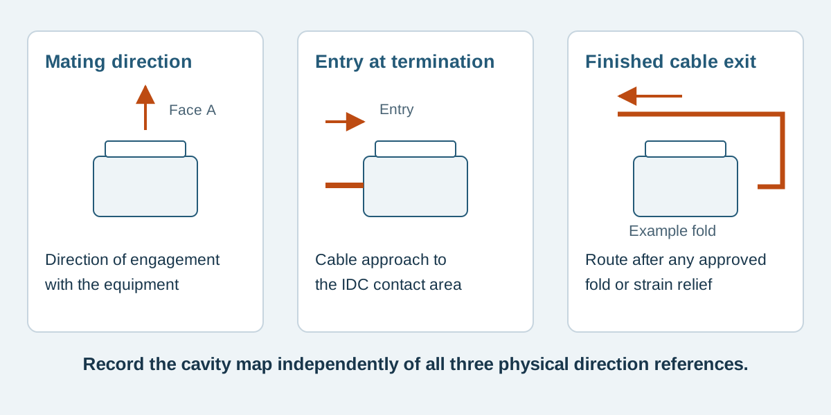
Conceptual illustration. Fictional examples are not approved product configurations, tooling instructions or inspection results.
Separate the three direction references
Name the connectors J1 and J2 before describing their arrangement. Then define the references below for each end. Use the selected connector drawing for contact numbering and the permitted assembly configuration.
Scroll sideways to read all columns.
| Reference | Question to answer | Useful drawing information |
|---|---|---|
| Mating direction | Along which direction does the cable connector engage the equipment? | Mating-face view, key reference and a mating arrow |
| Cable entry at termination | From which side does the cable approach the IDC contact area? | Side view showing body, cover and cable |
| Finished exit | Where does the cable run after any specified strain relief or fold? | Assembled side view and installation envelope |
| Electrical mapping | Which actual contacts are joined? | Explicit J1-to-J2 connection table |
A phrase such as “both connectors face the same way” omits the cable entry and final exit. “Reverse the second end” is even less precise: it may request a different physical arrangement, a different connection map, or both. Replace that phrase with an annotated view and identify what changes.
The existing pinout and viewing-direction guide explains face views and contact IDs. This article adds the cable route and termination arrangement rather than redefining the numbering.
Use an assembly option that belongs to the selected system
Manufacturer options demonstrate why one universal ribbon-cable orientation rule is inadequate. The 3M 891 technical drawing, sheet 1 describes a double-recessed cover that permits termination from either side. That feature belongs to that design; it does not authorize the same arrangement on an unrelated socket.
In a different system, the 3M 451 assembly guide, section 6 shows cable folded back over the cover before the specified strain relief is attached. Thus, the final exit can differ from the entry direction at the contact area.
Samtec also distinguishes several physical and wiring options in its IDC overview, page 12. An option name is not a substitute for the exact series drawing and a confirmed connection table. These references describe manufacturer systems, not Zeakka's production equipment or a promise to supply every illustrated option.
Compare routing changes against a fixed connection table
Consider the fictional teaching example EX-RB-01: a two-connector, six-conductor assembly. C1 through C6 identify continuous conductors. J1 and J2 each have contacts 1 through 6. These are conceptual labels, not a commercial connector's numbering pattern or a qualified component combination.
For the example's flat reference view, cable Face A faces the observer, J1 is on the left and J2 on the right, and the C1 reference edge is at the top. Both mating directions point toward Face A. J1's cable runs toward J2; J2's cable runs toward J1. In the shared worksheet example, their center datums are 180 ± 2 mm apart in this flat condition; that segment dimension is not the raw cable cut length. The drawing must still show the actual selected connector's mating face separately.
Scroll sideways to read all columns.
| Conductor | J1 contact | J2 contact | Intended relationship |
|---|---|---|---|
| C1 | J1.1 | J2.1 | One continuous net |
| C2 | J1.2 | J2.2 | One continuous net |
| C3 | J1.3 | J2.3 | One continuous net |
| C4 | J1.4 | J2.4 | One continuous net |
| C5 | J1.5 | J2.5 | One continuous net |
| C6 | J1.6 | J2.6 | One continuous net |
An installation drawing may then show the middle of this same cable routed around a bracket, while keeping the connector terminations unchanged. That routing change does not, by itself, change any row in the table. The permitted bend, available cable length and installation load still require review for the real cable.
Changing the connector's termination arrangement is a different proposal. If J2 must mate toward Face B or use a different entry side, ask for a revised assembly view and verify all six connections again. Do not infer a new map by mentally turning over a photograph, and do not assume that preserving the table is physically possible with any chosen connector.
Mark the reference edge without assigning an electrical function
An edge stripe is helpful when the drawing explicitly identifies the conductor beside it. In EX-RB-01, the reference edge identifies C1 because the example says so. It does not independently prove which real contact is pin 1 or which circuit carries a supply voltage.
Record the cable reference, stripe location and conductor-to-contact mapping together. A substitution involving cable marking, connector body or entry orientation needs review against those records. The color of the stripe cannot approve the change.
When comparing photographs, keep the named face and an orientation marker visible. A cropped close-up of a red edge cannot establish the arrangement of the complete assembly.
Review the finished envelope before approving the sample
Show the space occupied by the complete connector, cover, optional strain relief and cable route. Identify nearby walls, mating clearance and any service movement needed to unplug the connector. Use the finished configuration for this check, including folds that are absent from an unassembled part drawing.
Measure length from named datums, and state whether the assembly is flat or installed when a dimension is checked. Do not silently replace connector-to-connector length with a free-cable length after changing the exit. The ribbon cable specification worksheet helps keep these references together.
Ask the supplier to flag an unsupported entry option or unresolved routing requirement before making the sample. After sample review, retain the approved views with the connection table and revision so a repeat order has the same reference.
Orientation questions
Does folding the cable reverse its pinout?
A routing fold alone does not exchange electrical connections. It can change the apparent conductor order in a view. A different termination arrangement must be reviewed separately against the selected parts and connection table.
Can either side of any IDC socket accept the cable?
No general permission follows from the IDC name. Entry options, cover geometry and strain relief belong to the selected system. Confirm the exact configuration in its documents or with its manufacturer.
Is a photo enough to specify cable exit?
A photo can start the discussion, especially when it shows both ends and the route. Hidden contact numbering, termination details and required clearance may still need drawings and an explicit electrical map.
Send the connector views and the space constraint together
For custom flat ribbon cable assemblies, send the connector references, mating views, connection table and a sketch showing the required exits. Include quantity and available space. Zeakka coordinates supplier review and samples as a trading and sourcing partner; the actual component combination and assembly options require project confirmation. Contact Zeakka with the files you already have and mark unresolved details clearly.
Share this article
Help others discover this content