
IDC Ribbon Cable Inspection: What to Check Beyond Continuity
Table of Contents
A passing continuity result does not describe the physical condition of an IDC termination. A cover may be skewed, cable alignment may need review, or insulation may show damage while the intended contacts still conduct during a stationary test. Treat the electrical result and physical inspection as separate records.
The inspection reference must match the selected connector, cable and assembled options. This guide uses a named manufacturer's instructions to explain how to build that reference; it does not provide a universal IDC closure height or establish which production equipment Zeakka's suppliers use.
Inspect the physical termination as well as the circuit map
Illustrative inspection areas only. Actual cover, tooling, dimensions and acceptance criteria depend on the selected connector.
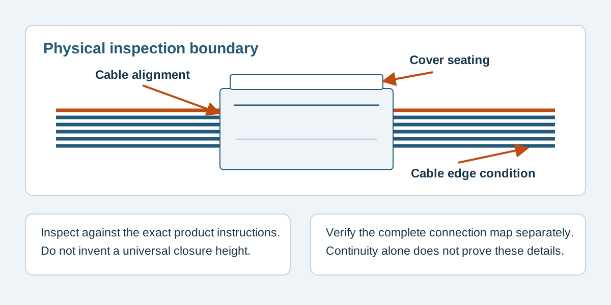
Conceptual illustration. Fictional examples are not approved product configurations, tooling instructions or inspection results.
Identify the assembly and its controlling documents
Start with the complete cable assembly part number and drawing revision. Record the connector and cover references, specified strain relief, cable construction and applicable assembly instruction revision. A photograph of a similar-looking socket is not an acceptance specification.
Find the assembly instructions as well as the component drawing and performance specification. Those documents serve different purposes. A catalog's electrical rating does not tell an inspector how a particular cover should appear after termination.
For example, the 3M 451 assembly instruction guide, section 5.3 checks cover seating and alignment, cable positioning and end retention. Section 6 covers the specified folded-cable strain relief. Apply these criteria to that documented configuration; they do not establish the requirements for other IDC products.
The 3M 891 product specification, section 7 separately includes a visual condition requirement addressing physical defects. Its qualification context should not be relabeled as a complete production inspection plan for another assembly.
Use the connector documentation guide if the available files do not clearly separate product drawings, assembly instructions and performance evidence.
Inspect alignment and closure from useful views
Use an unpowered, disconnected assembly and handling appropriate to the product. Do not pull the cable, open a cover or press it again merely to create a better photograph. Those actions can change the condition being investigated.
Plan the views before inspecting the lot. An overhead photograph can show the cable's lateral position but hide the relationship between the cover and body. An end view may reveal that relationship while concealing the opposite retention feature. Where a feature cannot be seen without disassembly, record that limitation.
Scroll sideways to read all columns.
| Inspection subject | What to compare with the selected reference | Evidence to record |
|---|---|---|
| Cable alignment | Required cable position at the termination | Top and side views with conductor-edge reference |
| Cover seating | Specified body-to-cover relationship | Views showing both sides rather than one visible corner |
| Retention features | Required engagement or end position | Close-ups of each relevant end |
| Cable edge and surface | Specified condition and visible physical damage | Location-marked close-ups, including the exit |
| Strain relief, if specified | Correct component, orientation and attachment | Side/end views of the complete fitted option |
| Finished cable exit | Approved routing, fold and clearance | Assembly view with the revision reference |
The table is an evidence-planning framework. It does not add numerical acceptance limits or replace the manufacturer's criteria. If the document requires a measurement, record its defined datum, method, instrument and result. Do not estimate a precision dimension from a perspective photograph.
A tooling shut-height setting and a finished connector dimension are also different references. Do not copy a number from a press setup table into an incoming-inspection limit. The tooling, locator and procedure must match that setup instruction; a photograph cannot verify the prior setup by itself.
Distinguish visible concerns from proven root causes
Record what is observed before explaining why it happened. “Cover appears higher at the right end in photo P02” is a useful starting observation. “Wrong press force” is a proposed cause that requires additional evidence.
Likewise, visible cable damage does not identify when it occurred. It may relate to preparation, termination, later routing or handling. Retain packaging and installation information when those stages could matter, and avoid changing the specimen before the supplier has reviewed the record.
Do not declare the hidden IDC interface acceptable solely because the outside looks aligned. Visual inspection examines accessible features. If additional examination is needed, agree the method and handling of the specimen with the responsible supplier or engineering team. Destructive examination should be distinguished from checks performed on units intended for shipment.
Keep the electrical result in its own column
Continuity asks whether the required nodes connect within the agreed method and limit. It does not establish cable alignment, cover retention or the condition of all insulation surfaces. A short-circuit result also does not establish a dielectric-withstand rating or insulation resistance under an unspecified voltage.
For a multi-connector cable, include the middle contacts in the test definition. An end-to-end pass can leave a middle IDC termination untested. See the multi-connector IDC guide for the complete-node example.
Link the electrical record to the same assembly revision as the physical inspection. Otherwise, a correct visual comparison and a passing wiring test may still refer to different configurations. The general testing guide explains the broader distinction between coverage, limits and test types.
Use a record that preserves unresolved items
The following fictional record illustrates documentation only. It describes no Zeakka shipment, real test result or qualified defect standard.
Scroll sideways to read all columns.
| EX-INSP-02 record item | Recorded observation | Status / next action |
|---|---|---|
| Assembly reference | EX-RB-02, teaching revision A | Fictional reference only |
| J2 cover relationship | Right side appears higher in P02; exact seating cannot be established from the available view | Hold for comparison with the selected assembly instruction and additional view |
| J2 far-end retention | Hidden by the photograph angle | Not inspected; obtain a suitable view |
| Cable near J3 exit | Surface nick visible in P03 | Preserve specimen and request disposition against the actual cable criteria |
| Wiring result | Report says pass against teaching map A; limits and program reference not supplied | Request the missing test definition; do not infer mechanical acceptance |
“Not inspected” is different from “pass.” So is “requires engineering review.” Preserve those distinctions when compiling a shipment record instead of converting every completed form field into an acceptance statement.
If a concern is confirmed, identify the affected unit and lot, segregate it under the agreed process and request a documented disposition. Rework permission and instructions must come from the applicable controlled process. Repressing or reopening a connector without that basis can damage parts and erase useful evidence.
IDC inspection questions
Can continuity prove that insulation is undamaged?
No. It verifies a specified connection condition. Accessible insulation needs its own visual review, and any required insulation-resistance or dielectric test needs a separately defined method and acceptance criterion.
Is there one finished height for IDC connectors?
No universal value applies. The selected connector drawing and assembly instructions define the relevant geometry; a press setting should not be mistaken for a general finished-height limit.
Can I approve a connector from one top photograph?
Only if the agreed inspection scope can actually be established from that view. Hidden retention features, side relationships and dimensions remain unresolved unless suitable evidence is provided.
Ask for the inspection reference with the cable quote
For custom flat ribbon cable assemblies, send the selected component references, drawing revision, required inspection points and requested records. Include photos of any concern with the connector and location identified. Zeakka is a trading and sourcing partner coordinating supplier review; additional inspections, methods and reporting requirements need project confirmation. Contact Zeakka to clarify the acceptance package before sample approval.
Share this article
Help others discover this content