
Ribbon Cable Assembly Specification Worksheet
Table of Contents
A ribbon cable specification needs to connect the physical layout to the electrical connection list. A conductor count and approximate length leave important questions unanswered: which connector is intermediate, which face is shown, where are the measurement datums, and which cavities belong to each net?
Download the editable ribbon cable specification workbook. It contains a blank specification, a two-ended fictional example, a three-position fictional example and short filling instructions. Use the amber cells in the blank sheet. The examples explain the fields; they are review requests with explicitly recorded open items, rather than manufacturing releases.
Build a specification that connects the drawing, BOM and netlist
The workbook contains a blank template and two fictional examples. Dimensions shown here are example requirements, not standard tolerances.
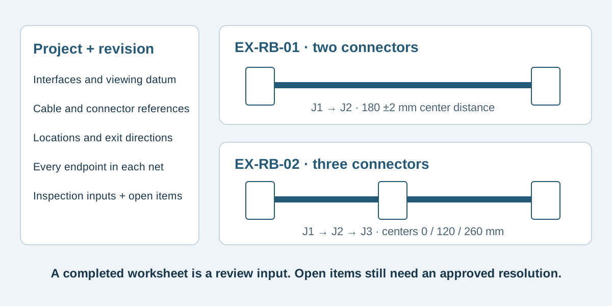
Conceptual illustration. Fictional examples are not approved product configurations, tooling instructions or inspection results.
Start with one configuration and one revision set
Enter the finished assembly identifier, drawing revision and BOM revision together. Use J1, J2 and J3 consistently on the layout, component list and electrical map. A connector reference that changes between documents makes the package ambiguous even when each file looks complete.
This worksheet is the ribbon-specific companion to the cable assembly BOM template. The RFQ checklist covers the wider commercial enquiry. Keep order quantity, application and approval scope visible, but resolve the actual assembly definition before treating a quotation as a production instruction.
Record the cable and every connector separately
Scroll sideways to read all columns.
| Input | What to record | Evidence to attach |
|---|---|---|
| Cable | Reference, conductor pitch, count, gauge, strand construction, insulation and relevant dimensions | Cable drawing or specification |
| Each connector | Exact reference, position label, cavity numbering and mating part | Part drawing and application instructions |
| Accessories | Cover, end cap and strain relief references, or an explicit reviewed exclusion | BOM and installation envelope |
| Placement | Named connector datum, segment dimension and tolerance | Flat-layout drawing |
| Route | Cable exit, installed folds, restraints and clearance | Installed-view sketch |
| Acceptance | Coverage, method, limits, revision and required records | Agreed inspection and test instructions |
Cable conductor pitch and connector mating pitch are different fields. For example, the 3M 891 drawing distinguishes its connector grid from the cable spacing and separately identifies strain-relief options. Use the selected system's documents to establish compatibility; those details cannot be inherited by an unrelated part. The pitch explanation covers the dimensional distinction. 3M 891 drawing
Read the two fictional configurations
All EX references are teaching labels, not orderable parts, approved component combinations or Zeakka product specifications. Both examples have six conductors, C1 through C6. Their illustrative cable pitch is 1.27 mm; the actual cable construction and connector combination remain subject to review.
EX-RB-01 has J1 at X = 0 and J2 at X = 180 mm. Its flat center-to-center segment is 180 ±2 mm. EX-RB-02 has J1, J2 and J3 at nominal X positions 0, 120 and 260 mm. Its two controlling segments are 120 ±2 and 140 ±2 mm. The nominal 260 mm span is derived from those segments, without adding a separate overall tolerance. These values illustrate documentation, not manufacturing capability.
Face A is the cable reference side facing the viewer when the cable is laid flat. The examples place all mating faces towards Face A and retain the C1 reference edge on the same side. J1 has cable exiting towards +X. In EX-RB-01, J2 exits towards −X. In EX-RB-02, J2 is a through position with cable on both sides, while J3 exits towards −X. The selected connector must support the proposed construction.
For each n from 1 through 6, the example map places Cn on J1 cavity n and J2 cavity n; EX-RB-02 also places it on J3 cavity n. Each row is one complete net. This is a stipulated fictional connection list, not a universal numbering rule for real dual-row IDC connectors. Check actual cavity IDs using the pinout and viewing-direction guide and the exact part drawing.
Keep cut length and installed folds explicit
The workbook gives cable cut length its own field. Both examples require the supplier to propose it from the selected connector and preparation drawing. It is not automatically 180 or 260 mm. Cable tails, connector geometry, trimming and preparation must be defined before cutting.
The baseline layouts contain no installed folds. For a folded route, add a separate installed view with fold location, direction, reference face and the chosen cable's bend guidance. A flat segment dimension alone does not show how the assembly fits inside the equipment.
Samtec's catalogue separately documents assembly length, wiring choices and physical orientation options. It illustrates why these inputs need explicit definitions; its options and limits do not qualify the EX examples. Samtec ribbon assembly catalogue
Close the open items before release
The examples assign four open items: selected component compatibility, operating conditions and installed envelope, cut-length preparation, and test requirements. Each has an owner, closure evidence and a point by which it must be resolved. A completed enquiry can contain known unknowns; a released manufacturing package needs the required decisions closed.
For continuity, list every intended endpoint of every net. For unintended connections, define the distinct-net coverage across all connector positions. A three-position cable needs J2 included, rather than checking only the first and last connectors. Record the approved method and its acceptance limits separately. The template invents no universal resistance, insulation or high-voltage threshold.
Use separate review, sample authorization and production release fields. No filled cell grants approval. Send the completed worksheet and available drawings for a custom flat ribbon cable assembly review. Zeakka coordinates sourcing and supplier review; specific components, construction and test scope are confirmed by project. Original branded components are considered within finished assemblies, and original loose parts are not sold separately.
Common questions
Can I submit the worksheet with unknown part numbers?
Yes, for an initial review. Mark unknowns explicitly, attach available photos or mating references, and assign the required follow-up. Do not convert an unconfirmed candidate into an approved BOM entry.
Does a red cable edge identify cavity 1?
Only a documented assembly definition establishes that relationship. Record the cable conductor identifier and verify the actual cavity map and view. A colored edge alone cannot prove the connection.
Can I add more intermediate connectors?
Extend the worksheet to record every proposed position in the layout, BOM and applicable net rows, then extend endpoint test coverage. Each added connector still requires review of component suitability, placement, clearances and preparation.
Share this article
Help others discover this content