
Multi-Connector IDC Ribbon Cables: Specifying the Intermediate Connections
Table of Contents
A ribbon cable with an intermediate IDC connector needs more than an overall length and an end-to-end pinout. The middle connector introduces its own location, orientation and electrical contact to each required conductor. Testing only the two end connectors can leave that added termination outside the test coverage.
Define the physical layout and complete net list together before requesting a quotation. This guide uses a fictional three-connector example to show the missing details. It does not propose an interface standard, qualify a bus topology or establish that a particular configuration is available from Zeakka.
Record every intermediate connection and position
EX-RB-02 is a fictional continuous six-conductor assembly. The drawing is not a real connector footprint or scale drawing.
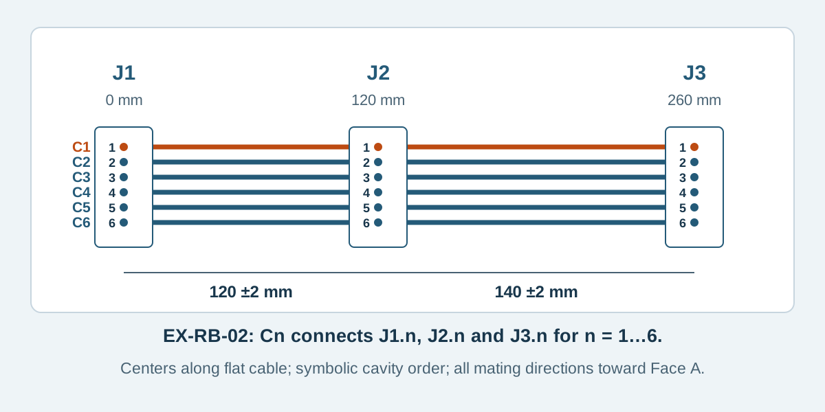
Conceptual illustration. Fictional examples are not approved product configurations, tooling instructions or inspection results.
Establish whether the conductors continue through the middle
First state what happens to the cable at the intermediate connector. In the continuous-cable example below, each conductor remains uncut between the two ends, and the middle connector contacts that same conductor. This differs from a split branch, a splice or separate cable segments joined inside a housing.
The distinction affects the drawing, assembly review and electrical test definition. A visual line passing a connector on a schematic is insufficient unless the intended electrical junction is explicit.
Manufacturer systems can offer multiple configurations. Samtec's IDC overview, page 12 illustrates daisy-chain and other wiring arrangements. That overview is evidence that such options exist within manufacturer offerings, rather than permission to add an arbitrary middle connector to any IDC family. Obtain the exact series documents and confirm the proposed build.
For the earlier choice between IDC and individual crimped ends, use the IDC versus crimp guide. Here, the decision is how to define an already proposed multi-connector IDC layout.
Dimension the intermediate connector from explicit datums
EX-RB-02 is a fictional six-conductor assembly with connectors J1, J2 and J3. It is not an orderable part number. For this teaching example, all connector mating directions point toward cable Face A. In the flat reference view, Face A faces the observer, J1 is leftmost and the C1 reference edge is at the top.
Define a transverse center datum at each connector's termination location. The X direction runs along the flat cable from J1 toward J3. The values below illustrate a dimension scheme, not recommended production lengths or tolerances.
Scroll sideways to read all columns.
| Feature | Example definition |
|---|---|
| J1 center datum | X = 0 mm; origin |
| J2 center datum | Nominal X = 120 mm |
| J3 center datum | Nominal X = 260 mm |
| J1-to-J2 center distance | 120 ± 2 mm |
| J2-to-J3 center distance | 140 ± 2 mm |
| J1-to-J3 nominal center distance | Derived 260 mm; no separate overall tolerance specified |
| Cable run at each connector | J1 toward +X; J2 toward −X and +X; J3 toward −X |
The two segment tolerances govern this example. Do not add a conflicting overall requirement without deciding which dimensions control acceptance. If installed board positions require a tighter relationship, revise the dimension scheme deliberately rather than expecting a flat cable to absorb an undefined mismatch.
These are center-to-center dimensions, not raw cut length or cable-edge-to-housing dimensions. The supplier needs the selected parts and permitted cable projection to determine manufacturing details. Cable tails beyond the connector centers remain undefined in this example and would need agreement for a real build.
List all three contacts on every intended net
C1 through C6 are conductor IDs. Contact labels below belong to the fictional example; their numeric sequence does not represent the mating-face layout of a commercial connector. Use actual cavity numbering from the selected part drawings for production.
Scroll sideways to read all columns.
| Net / conductor | J1 contact | J2 contact | J3 contact | Cable relationship |
|---|---|---|---|---|
| N1 / C1 | J1.1 | J2.1 | J3.1 | Continuous, uncut conductor |
| N2 / C2 | J1.2 | J2.2 | J3.2 | Continuous, uncut conductor |
| N3 / C3 | J1.3 | J2.3 | J3.3 | Continuous, uncut conductor |
| N4 / C4 | J1.4 | J2.4 | J3.4 | Continuous, uncut conductor |
| N5 / C5 | J1.5 | J2.5 | J3.5 | Continuous, uncut conductor |
| N6 / C6 | J1.6 | J2.6 | J3.6 | Continuous, uncut conductor |
All three contacts in a row must belong to the same net. Different rows are intended to remain electrically separate. There are no intentional cross-connections, omitted contacts or grounded conductors in this teaching example, and the net names do not assign signal functions.
If the equipment requires a different middle mapping, show it explicitly and review whether the selected construction can realize it. Do not change one table cell while leaving a diagram that still shows six uninterrupted, directly tapped conductors.
Include every middle contact in the test definition
For N1, checking J1.1 to J3.1 establishes an end-to-end path under the agreed test conditions. It does not establish that J2.1 contacts that conductor. A poor or absent J2 termination could coexist with a passing end-to-end result.
The test definition must include J1.1, J2.1 and J3.1 as accessible nodes of N1. Apply the same requirement to N2 through N6: all 18 connector contacts enter the fixture mapping. Define coverage that establishes every required node's connection to its intended net, and checks for unintended connections between nets.
This is a coverage requirement, not a universal instruction to test every pair separately. The supplier should describe how its fixture and test program establish the complete net list, with project-specific limits. A tester fixture omitting J2 cannot prove its connections simply by reporting “100% tested.”
Use the cable assembly testing guide to distinguish continuity and short checks from additional electrical or mechanical requirements. Multi-connector coverage does not turn a wiring test into a signal-integrity or system-function qualification.
Review installation and application constraints separately
A physically continuous ribbon can create electrical branches or stubs at connected equipment. Whether that topology is acceptable depends on the actual interface, drivers, loads, operating conditions and system design. Connector count alone cannot establish suitability for a communication bus, high-speed signal or power circuit.
Also review the middle connector's mating clearance, installation sequence and restraint. The cable may be dimensioned flat while the finished route passes around a bracket. State both references; the distance between installed boards is not automatically the required flat segment length.
If one connector must face the opposite side, treat it as a specific configuration change. Obtain the revised termination drawing and confirm the contact mapping, cable path and assembly feasibility together. The IDC orientation guide provides the direction references.
Multi-connector questions
Does a middle IDC connector automatically split every circuit?
The approved drawing must say which contacts join which conductors. This example taps all six continuous conductors, but that relationship cannot be assumed from the presence of a connector alone.
Can I specify only the total length?
That leaves the middle location uncertain. Define its datum, segment dimensions and tolerances, with an explicit flat or installed measurement condition.
Is testing the first and last connector sufficient?
It leaves the intermediate termination unproven. Include every required connector contact in the fixture mapping and establish its intended net membership.
Request a review of the complete connector chain
Use the ribbon cable specification worksheet to record every connector, segment and net. For custom flat ribbon cable assemblies, send Zeakka the drawing revision, component references, full connection table, quantity and application requirements. As a trading and sourcing partner, Zeakka coordinates feasibility review with suppliers before confirming the proposed configuration. Send your cable details, including any unknown middle-connector dimensions or orientation.
Share this article
Help others discover this content