
JST SH vs SR: Crimp or IDC for a 1.0 mm Connection?
Table of Contents
JST SH and SR use a 1.0 mm pitch, with different wire-termination methods: SH uses crimp contacts; SR uses insulation displacement, or IDC. Unlike unrelated connector families that happen to share a pitch, these two have a documented relationship. JST lists SH and SR as compatible series, and specific original SMT headers appear in both catalogs.
Quick choice: start with the exact board header, then decide whether the cable needs a crimp-based SH construction or the specified SR IDC construction. Shared mating hardware does not make their wire preparation, current ratings or finished cable dimensions identical.
What changes on the cable side?
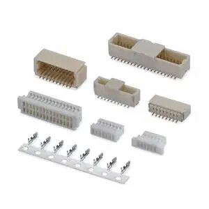
SH alternative catalog components. This image shows the crimp-style side of the discussion; it does not show SR IDC parts or establish SH/SR header compatibility. View SH alternatives.
The following original JST references were checked on 7 October 2026. They do not specify Zeakka alternatives or rate a finished assembly.
Scroll sideways to read all columns.
| Item | SH | SR |
|---|---|---|
| Pitch | 1.0 mm | 1.0 mm |
| Termination | Separate crimp contact in housing | IDC socket |
| Catalog current | 1 A AC/DC with AWG 28 | 0.7 A AC/DC |
| Voltage | 50 V AC/DC | 50 V AC/DC |
| Wire | AWG 32–28 | AWG 30, seven-strand tin-coated annealed copper |
| Insulation outside diameter | 0.4–0.8 mm | 0.54–0.58 mm |
| Four-circuit cable-side example | SHR-04V-S with SSH-003T-P0.2-H | 04SR-3S |
See the SH specifications and contact table, pages 1–2 and SR/SZ specifications and socket table, pages 1–2.
Are SH and SR compatible?
For a concrete original-JST example, both catalogs list BM04B-SRSS-TB as a four-circuit top-entry SMT header and SM04B-SRSS-TB as the side-entry version. The SH header note explicitly permits an SR IDC socket. Together with the cable-side examples above, these listings establish a specific shared mating arrangement. SH header table and note, page 3; SR/SZ header table, page 3.
JST's SH product profile also identifies compatible SR IDC and SZ through-hole options. This is a reason to check the intended combination, not a blanket approval for every 1.0 mm header. Verify the complete part number, circuit count and variant. Alternative-brand connectors need their own evidence; the original JST compatibility note does not qualify them.
A production drawing should name both mating parts. “SH/SR compatible” is useful background, but it is too broad to control the actual interface by itself. Retain the specific header identity when reviewing a replacement cable, especially if the board cannot change.
Preserve circuit numbering when changing the termination
A mechanically valid connection can still carry the wrong signals. Before comparing wire colors, fix the viewing direction: mating face, wire-entry side and PCB mounting surface are different views. Do not copy a left-to-right sequence from one photograph into a drawing showing another face.
JST's PCB layout notes use the connector mounting surface as the viewing reference. Use the marked No. 1 circuit and the relevant part drawing to map each conductor to the board net. Include a clear view label on the cable drawing and verify the completed pin map by continuity testing. SH layout, page 1; SR/SZ layout, page 2.
This matters even when both cable ends look alike. A photograph establishes appearance; it does not establish which conductor reaches which circuit at the other end.
SR needs a defined wire and IDC process
Treat an SR design as a socket, wire and termination-process combination. The listed gauge does not authorize any wire sold as AWG 30. Confirm the actual conductor construction, insulation diameter and applicable wire specification before approving a build.
Use tooling and process instructions confirmed for the selected SR socket and wire. Do not choose SR on the assumption that it can be assembled by pressing arbitrary loose wires into the connector with a generic tool. Obtain the applicable JST processing instructions and tooling recommendation before process approval; this guide does not prescribe a tool model or setup.
Nor is an SR socket an SH housing into which a loose crimp terminal can be substituted. If the cable requires a change from IDC to crimp, specify a complete, compatible SH cable-side construction and assess its effect on the assembly. That is a termination-design change, even when the board header remains the same.
For SH, the corresponding manufacturing review concerns the selected contact, wire fit, crimp tooling, termination quality and contact seating. Choose between the constructions according to the available qualified process and the cable requirements, rather than assuming that one assembly method is always simpler or cheaper.
Check clearance and loading again
The SH catalog's illustrated top-entry assembled height is 6.3 mm; its side-entry reference is 2.95 mm. SR's SMT illustrations show 4.9 mm for top entry and 2.95 mm for side entry. Use the complete drawing for the selected orientation, including depth and wire exit; a common header does not guarantee an unchanged cable envelope. SH page 1; SR/SZ page 2.
Likewise, do not carry the SH headline current into an SR cable specification. Check the actual circuit load and installed conditions against the selected construction. If a change is intended only to simplify routing, make sure it does not also introduce an unreviewed electrical change.
Review the cable you need
Zeakka is a connector and cable-assembly sourcing business. Its existing SH-series alternative connector page provides a starting point for alternative components. Original JST parts are offered within finished cable assemblies, subject to confirmed project scope. SR-specific wire, tooling and assembly availability require confirmation; this comparison does not establish an SR supply capability.
For a proposed alternative, follow the connector-alternative verification guide. To assess an SH/SR cable change, send the existing header identity, wire specification and labeled pin map. Those details establish whether the proposal preserves the board interface while changing the cable construction appropriately.
Related selection guides
Connector Housings, Terminals and Headers Explained · Wire-to-Board vs Wire-to-Wire Connectors: Choosing the Connection Layout
Share this article
Help others discover this content