
Wire-to-Board vs Wire-to-Wire Connectors: Choosing the Connection Layout
Table of Contents
Choose the connection layout by deciding where the equipment should come apart. A wire-to-board connection provides a detachable interface at a printed circuit board. A wire-to-wire connection provides a detachable interface between two wired sections. An assembly can use both: a board connection inside the enclosure and an in-line disconnect near a replaceable module.
Quick choice: start with wire-to-board when the cable should disconnect at the PCB. Add or choose wire-to-wire when the service boundary belongs elsewhere along the cable route. Then check space, access and cable support around the complete connection.
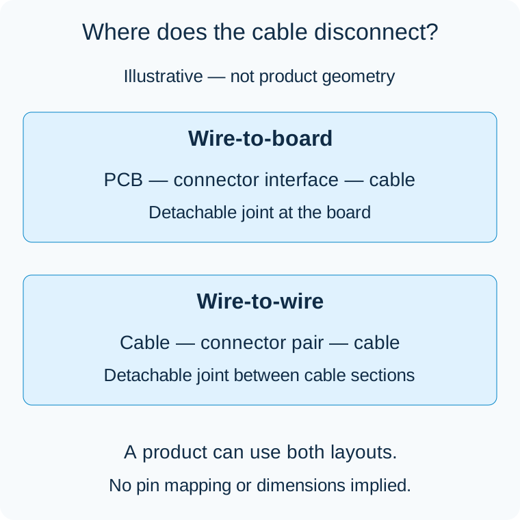
Illustrative connection layouts, not product photographs or dimensional drawings.
What each layout changes
Scroll sideways to read all columns.
| Design question | Wire-to-board | Wire-to-wire |
|---|---|---|
| Where is the detachable interface? | At the PCB-mounted mating component | Between two wired sections |
| What anchors its position? | The board location and header orientation | Cable routing, a support or a compatible panel mount |
| What space must be reserved? | Board footprint, mated height, cable exit and removal path | Mated housing envelope, support points and separation space |
| What can be replaced independently? | The cable or attached module can detach from the board | A cable segment or module can detach from the remaining harness |
| What is the main layout constraint? | Access around the board and neighboring components | Control of the disconnect's position along the route |
For a concrete example, the original JST PH catalog describes a wire-to-board system with top-entry and side-entry headers. The original JST SM product profile describes a wire-to-wire system. These examples explain the layouts; they do not establish interchangeability or the specifications of alternative components.
Start at the board when the PCB interface is fixed
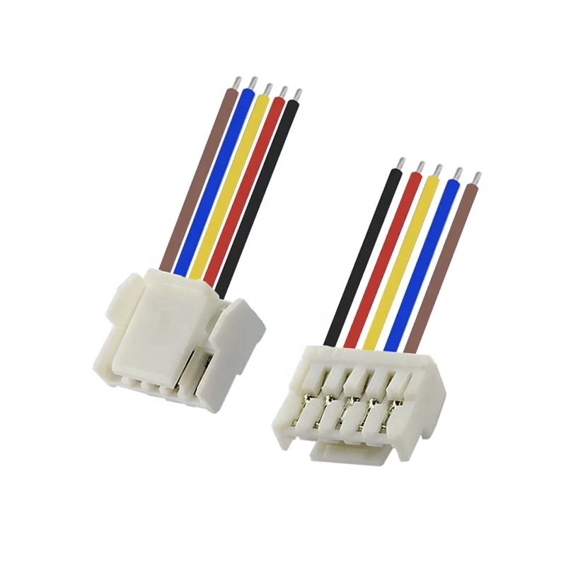
GH alternative cable ends for a wire-to-board arrangement. The PCB-side mating connector is not shown. View GH alternatives.
If a board has already been released with a particular header, the cable must match that interface. Identify the mating housing and terminal before choosing cable routing. A wire-to-wire connector positioned farther along the lead does not remove the need for the correct board connection.
For a new board, evaluate the mating direction early. A top-entry connection needs room above the board to engage and remove the cable housing. A side-entry connection needs room along the insertion direction. The direction that looks compact in a board drawing may become inaccessible once the board is installed in its enclosure.
Include adjacent components, the enclosure wall and the technician's hand or permitted service tool in that review. The connector body fitting within the available space is only one part of the decision. Check the cable's route after it leaves the housing, including any turn toward an opening or support point.
Put an in-line disconnect at a useful service boundary
SM alternative catalog housings and contacts illustrate components used for wire-to-wire arrangements, not a completed installed connection. View SM alternatives.
Wire-to-wire is useful when a removable part should separate without reaching the main PCB. A door-mounted control panel, for example, can have a disconnect near its service opening. The remaining harness can stay routed inside the enclosure while the panel is removed. This is a layout example, not a recommendation for a particular connector family or environmental rating.
Place that disconnect where both halves can be reached and held. Reserve enough separation distance to unplug the pair before trying to move the module away. If the connector ends up behind a fixed bracket, the supposed service benefit may disappear.
Cable length on either side also matters. Too little length prevents access; unmanaged excess can interfere with a hinge, fan or cover. Define the service position as well as the normal installed position, and retain the cable where needed to keep it out of moving parts.
Use both layouts when they solve different problems
Consider a controller connected to a replaceable sensor module. The board interface can remain fixed while an in-line connector defines the sensor's removal point. This arrangement may let a technician replace the sensor without disturbing the board connector.
The additional disconnect also introduces another pair of mating components, terminations and space requirements. Compare that extra material and assembly work with the expected service benefit. A product opened only for major repair may not need the same service boundary as a module changed regularly.
Avoid adding disconnects simply to make every cable segment removable. Give each connection a purpose: board assembly, enclosure assembly, module replacement or a defined maintenance operation. The best arrangement is the one that supports those operations with manageable routing and access.
Design support and retention separately
A connector's mating retention keeps its halves engaged. Cable support controls how forces from the harness reach that connection. Both need attention. A board header should not become the unintended anchor for a heavy cable, and an in-line pair should not move freely into an abrasive edge.
Panel mounting is one possible positioning method for a compatible connector; it does not turn a wire-to-wire system into a PCB interface. Follow the selected housing's mounting requirements, and leave access to any release mechanism. For other arrangements, assess whether a cable clip or support near the disconnect can maintain the intended position.
The cable strain-relief guide covers support and protection choices in more detail. Do not assume that an overmold, sleeve or latch can substitute for every other form of mechanical support.
Review the layout as an assembly sequence
Before finalizing the design, walk through installing the board, routing the cable, mating each connector, closing the enclosure and replacing the serviceable part. Identify any step that requires pulling a wire, bending it sharply or reaching a release that is no longer accessible.
Show the normal cable route and the intended disconnect location in the assembly drawing. A simple installed-view sketch can communicate a service boundary more clearly than connector names alone. Include any required keep-out region around the mating path. The cable assembly drawing guide explains how to organize the resulting definition.
Explore the appropriate connection route
Browse wire-to-board connectors for a PCB interface or wire-to-wire connectors for a cable-to-cable disconnect. For a harness combining those interfaces, discuss the layout through custom discrete-wire cable assemblies.
Zeakka is a trading and sourcing partner. Identify whether the project requires original-brand components within a finished cable assembly or permits evaluation of clearly identified alternatives. Original-brand connectors are not offered as standalone components. Family references help define the interface; the proposed parts still need evidence appropriate to the actual assembly and application.
Related selection guides
Connector Housings, Terminals and Headers Explained · JST SM vs RCY: Choosing a Wire-to-Wire Connector
Share this article
Help others discover this content