
JST SM vs RCY: Choosing a Wire-to-Wire Connector
Table of Contents
JST SM and RCY both connect one wired assembly to another. Start with the required circuit count, retention method and location of the disconnect. SM offers a wider choice of circuit counts and a locking arm; RCY is a compact two-circuit option with friction retention. A shared pitch does not make their housings interchangeable.
Quick choice: retain the correct mating family when replacing an existing cable. For a new design, consider SM when the connection needs an accessible release latch, more than two circuits or panel mounting. Consider RCY for a two-circuit free-hanging connection where its retention and envelope meet the application requirements.
Compare the original JST systems
These references describe original JST components. They do not specify the performance of an unbranded alternative or establish the rating of a finished cable assembly.
Scroll sideways to read all columns.
| Selection point | JST SM | JST RCY |
|---|---|---|
| Contact pitch | 2.5 mm | 2.5 mm |
| Catalog circuit counts | 2 through 12, plus 18 | 2 |
| Retention | Secure lock with an arm mechanism | Friction lock |
| Mounting arrangement | Panel-mounted or free-hanging | Free-hanging |
| Published conductor sizes | AWG 28, 26, 24 and 22 | AWG 28, 26, 24 and 22 |
| Listed insulation outside diameter | 1.2–1.8 mm | 1.2–1.8 mm |
Sources: JST SM product profile, SM catalog and JST RCY product profile.
Match the disconnect to the equipment
For a multi-conductor module, using one connector can keep the associated circuits together during assembly and service. SM is a candidate when that grouping requires more than two positions. Decide how many circuits the module actually needs before comparing housing sizes; splitting a larger connection across several two-position plugs changes the assembly and servicing process.
For a two-conductor detachable lead, RCY is a candidate when an in-line connection suits the routing. Check where the coupled housings will rest, whether nearby parts can press against them, and whether the connection remains accessible after the cover is fitted. A small connector hidden behind a bracket may be harder to service than a larger connector placed within reach.
An existing mating connector usually determines the family. Changing the cable side alone to a similarly spaced housing is not a valid substitution. A redesign should identify both mating halves and consider whether the equipment side can also change.
Give the retention mechanism room to work
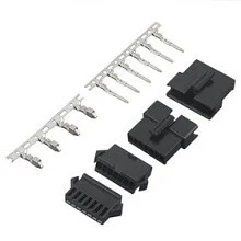
SM alternative catalog housings and contacts. This is not an RCY image or evidence of interchangeability. View SM alternatives.
SM's latch needs clearance for both engagement and release. Position it so an assembler can check that the connection is seated and a technician can operate the release without pulling on the wires. Panel mounting can establish a repeatable location, but the panel cutout and housing must follow the selected component drawing.
RCY's friction retention changes how the disconnect is handled. Plan access to the housings themselves, and keep cable tension from becoming the normal separating force. Do not treat either connector as a cable clamp. A nearby support point can control the cable route without transferring movement directly to the contact terminations.
Neither a latch nor a friction fit, by itself, proves suitability for a particular vibration, outdoor or repeated-service requirement. Those conditions belong in the component and assembly selection, with evidence for the proposed configuration.
Specify the terminal and wire together
The SM catalog lists SYM-001T-P0.6 pin contacts with SHF-001T-0.8BS socket contacts. RCY lists the same pin-contact reference but SYF-001T-P0.6 socket contacts. The different socket contact is a practical reminder that a common pitch or one shared part number does not establish a common mating system. See the contact tables in the SM catalog, page 2 and RCY catalog, page 2.
Conductor size and insulation diameter are separate checks. A wire can have the expected AWG yet have insulation that is unsuitable for the selected termination. Identify the actual wire construction and match it to the contact specification; do not enlarge the allowed range from a generic family description.
Current also needs context. The SM catalog lists 3 A for its 2–12-circuit versions and 2 A for the 18-circuit version. The RCY catalog lists 3 A at AWG 22, 2 A at AWG 24, 1 A at AWG 26 and 0.5 A at AWG 28. These are original-component references, not a blanket cable rating. Review the finished assembly's wire, operating temperature and installation before assigning its usable current. Sources: SM housing tables, pages 3–5 and RCY current table, page 1.
Source the selected configuration clearly
Zeakka supports connector and cable sourcing as a trading and sourcing partner. Its SM connector alternative and RCY connector alternative listings should be reviewed against the proposed parts and mating samples. Original JST catalog data must not be transferred to those alternatives as a performance guarantee.
For an assembly using original JST components, discuss the complete cable requirement through custom JST cable assemblies. Original components are supplied only within finished cable assemblies, not as standalone connector sales. State whether an original-component assembly is required or a clearly identified alternative may be evaluated. The connector alternative verification guide explains the evidence needed for that separate decision.
Common questions
Can a two-pin SM cable plug into RCY?
Do not select that combination. Matching pitch and circuit count do not establish matching housings, socket contacts or retention geometry. Specify a complete approved mating pair.
Is SM always the better choice because it has a latch?
The latch is useful only when it suits the assembly and remains accessible. RCY may suit a two-circuit connection with appropriate cable support; SM may suit a connection needing its retention or mounting options. Check the installation rather than choosing by the family name alone.
Related selection guides
Wire-to-Board vs Wire-to-Wire Connectors: Choosing the Connection Layout · Connector Polarization vs Keying: Preventing the Wrong Connection
Share this article
Help others discover this content