RCY to prepared wire ends
Identify the RCY half and specify the two free ends: cut length, strip length and any required end treatment. Include where those ends connect in your equipment.

Two-circuit · Wire-to-wire · Project-based sourcing
Source finished RCY cable assemblies with a defined mating pair, polarity, wire specification and length. Send your drawing or sample requirements; Zeakka coordinates supplier review, quotation and sample approval as your trading and sourcing partner.
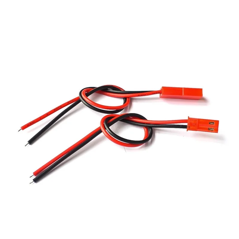
Use these arrangements to describe your requirement. They are quotation inputs, not a list of pre-approved stock assemblies. The connector at the other end, wire preparation and application must be reviewed together.
Identify the RCY half and specify the two free ends: cut length, strip length and any required end treatment. Include where those ends connect in your equipment.
For an extension or interconnect, identify the exact half at each end and the cavity-to-cavity map. State whether the order includes a separate mating lead or only one finished assembly.
Provide the opposite connector, terminals and pin assignment. Similar wire colors or a matching pitch do not establish electrical compatibility between different systems.
The original RCY family is a two-circuit wire-to-wire system with 2.5 mm pitch. Color and pitch alone cannot identify the correct mating pair. Compare the housing, latch, contacts and drawing before selecting a candidate.
Compare both halves from the mating face and the wire-entry side. Use the photographs to describe your requirement, then identify the exact housings, contacts and circuit map on the assembly drawing.
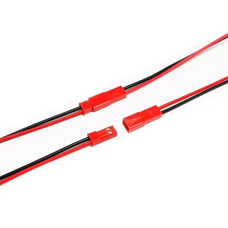
The upper pair is connected; the lower pair shows the two halves separated. Distinguish a pair of separate leads from a single cable with RCY connectors at both ends when defining the order.
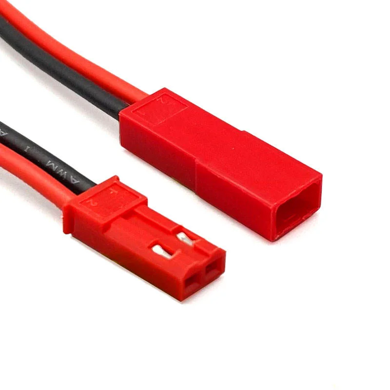
Check the mating openings, housing profile and contact retention details against the selected parts. Housing color and wire color alone do not establish compatibility or polarity.
01
Provide both housing references, matching terminals and the equipment-side connector. State whether original JST components are required or an unbranded candidate may be reviewed.
02
Identify each cavity using a named viewing direction. List the connection from each cavity to the other end, wire color and circuit function. Do not infer polarity from a red housing or red/black wires.
03
Specify conductor size, insulation material, outside diameter, temperature requirement and any required wire documentation. Wire gauge alone does not establish terminal compatibility.
04
Define the measurement datum, finished length and tolerance. For open ends, state strip length, tinning or other preparation only where required by the approved design.
05
Supply operating current, voltage, ambient conditions, routing and handling loads. The applicable limit belongs to the selected terminal, wire and assembled design, not the family name alone.
06
Include sample quantity, first order, repeat demand, target date and drawing revision. Agree the sample checks, packing, labels and required records before production release.
Use the connection list template for the electrical map and the assembly BOM template for housings, contacts and wires. If the connector is uncertain, start with the connector identification worksheet.
Review both connector halves, contact selection, sourcing restrictions and open requirements. Keep unresolved values visible in the quotation instead of treating a reference photo as a complete specification.
Define continuity, absence of unintended connections, polarity, dimensions and any application-specific acceptance checks. Where applicable, agree the pull-force or dielectric test requirements, acceptance limits and test conditions for the specific assembly.
Compare the sample and mating equipment with the drawing revision. Record any approved change to length, wire, contacts or sourcing before repeat production. Keep labels and packaging tied to that revision.
For the viewing direction and cavity labels, see the pinout guide. Use the sample approval checklist to record the release decision.
The JST RCY family is a two-circuit, 2.5 mm pitch wire-to-wire system. Both mating halves terminate wires. It is not an XH board header with a similar pitch. Verify the exact housings and contacts for your assembly.
Yes, you can submit an RCY-to-RCY layout for quotation review. Define the housing and contact at each end and every connection between them. An extension lead, a mating pair of separate leads and a loopback assembly are different deliverables; a drawing should make the intended arrangement explicit. Feasibility is confirmed for the submitted design.
State your sourcing requirement in the RFQ. Original JST components may be sourced within a finished cable assembly, subject to availability and quotation. An unbranded candidate needs its own drawing and sample approval; it is not automatically interchangeable or covered by the original manufacturer's ratings. This page is for finished assemblies, not loose original JST parts.
Send the application requirements and exact terminal reference. We review the combination of terminal, conductor, insulation and operating conditions before confirming a proposal. A catalogue candidate's figures and an original JST specification must not be mixed to create an assembly rating.
A photo can help identify the housing and latch, but it cannot confirm hidden connections or electrical polarity. Add clear mating-face and wire-entry views, cavity labels and a connection list. When a sample is the source, agree how its connections will be documented and approved.
Quantity and timing depend on component sourcing, wire preparation, assembly requirements and sample approval. Provide sample and production quantities together so the quotation can distinguish development needs from repeat supply.
Include the mating pair, circuit map, wire, length and quantities. If you only have a sample, describe what must stay the same and which requirements still need confirmation.