
Multicore Cable vs Discrete-Wire Harnesses: Choosing the Construction
Table of Contents
A connector pinout can be wired using a jacketed multicore cable or a harness assembled from individual insulated wires. Both may connect the same circuits, but their routing, branch preparation and termination details can differ substantially.
Choose the construction around the installed route, termination and support requirements.
Define the two constructions
In this guide, multicore cable means several individually insulated conductors contained within a common outer jacket. Discrete-wire harness means an assembly of separately insulated wires, arranged and restrained according to its drawing. That harness may include protective sleeving or other coverings; it is not necessarily an uncovered bundle.
This comparison concerns the complete assembly. Solid versus stranded and insulation versus jacket are separate decisions.
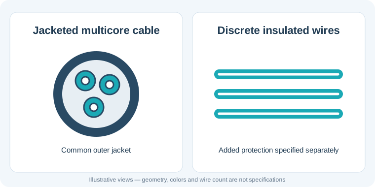
Conceptual construction diagram; quantities, dimensions and colors do not specify a product.
Manufacturer data sheets show why “multicore cable” alone is insufficient for a specification. Alpha Wire's 6336 construction lists individual conductors, a color code, an overall jacket and a finished diameter. Those details belong to that exact cable, rather than every cable with the same conductor count. Alpha Wire 6336 construction
Start with the route and branch points
A common jacket keeps conductors together along the jacketed run. Near a connector, the jacket must end so the individual wires can reach their terminals. A longer fan-out may be needed where those wires go to separate destinations.
Define that transition on the drawing: jacket removal length, wire lengths beyond the jacket, branch locations and required protection or support. Avoid treating the breakout as spare wire that the assembler can arrange freely. Its geometry affects installation and the space behind the connectors.
Discrete wires can be assigned different paths and branch lengths without first emerging from one common jacket. They still need a controlled layout. Specify bundle restraints, branch exits and any covering; installation should not depend on someone interpreting a loose set of wire lengths.
Use a decision table before choosing parts
Scroll sideways to read all columns.
| Project question | Jacketed multicore cable | Discrete-wire harness |
|---|---|---|
| Do most circuits share one route? | Evaluate a common cable run with defined end breakouts | Define how the separate wires remain organized along that route |
| Are destinations spread through the equipment? | Check whether jacket transitions and fan-outs suit every destination | Define each branch and its restraint arrangement |
| Do circuits need different wire specifications? | Check the actual cable construction; do not assume every core is identical | Specify each wire separately and verify its terminal compatibility |
| Is installation space restricted? | Use the actual cable diameter, breakout envelope and routing limits | Evaluate the finished restrained bundle, branches and protection |
| What reaches the connector? | Individual core insulation and conductor details still matter | Check each selected wire against its terminal requirements |
| What must purchasing control? | Exact cable identification plus assembly components | Individual wire specifications plus assembly components |
Neither construction is automatically smaller, cheaper or suitable for higher current. Evaluate the actual components and installation conditions rather than inferring performance from the construction name.
Compare wire sizes and identification
Record the required wire specification for each circuit. A stock multicore cable may suit those requirements, or its available conductor combination may leave a mismatch. Mixed constructions exist, but availability and suitability must be established for the selected part.
With discrete wires, the drawing can assign different gauges, insulation specifications or colors to particular circuits. That freedom also creates more items to control. Document permitted substitutions and do not replace a wire solely because its gauge matches.
For either option, map wire identification to connector cavities. A manufacturer's core color sequence does not establish your equipment pinout. Resolve repeated colors, stripes or numbered cores explicitly, including the viewing direction used in connector drawings.
Measure the finished assembly envelope
Compare more than the straight section. Include the jacket end, the fan-out, connector rear exits, support points and any sleeve or heat-shrink transitions. A compact cable can still require substantial space where its cores separate.
For a discrete-wire harness, evaluate the restrained bundle rather than adding wire diameters and calling the result its installed size. Arrangement, coverings and branches affect the envelope. Use a sample or documented layout where fit is important.
Routing limits belong to the selected components and operating conditions. Alpha Wire's 79251 data separates static and dynamic bend-radius conditions, illustrating why a generic rule for all multicore cables is inappropriate. Alpha Wire 79251 properties
Check termination and support at both ends
Confirm conductor size, stranding, insulation diameter and preparation against the selected terminal's application requirements. An overall cable diameter does not establish whether its individual cores fit a crimp contact. Conversely, terminal compatibility alone does not establish that the cable fits a clamp, gland or connector backshell.
Review where mechanical support acts. A jacket clamp and individual-wire support are different arrangements. Specify the intended support surfaces and breakout geometry, and assess installation forces without assuming that either construction inherently protects the terminals better.
Control the bill of materials and approve a sample
For multicore construction, identify the cable part or complete agreed specification, then document the jacket preparation and core-to-cavity mapping. For discrete construction, identify each wire and the components that organize or protect the finished harness. Both need connector and terminal identification, drawing revision and approved alternatives.
Fictional example: a control module connects to a nearby panel and two sensors at different locations. One proposed assembly uses jacketed cable with an extended fan-out. Another uses separate branches from a restrained wire bundle. These are illustrative options, not a Zeakka customer project.
The buyer compares both samples in the enclosure: panel entry, branch reach, service access and connector engagement. The selected construction follows that fit review and the circuit requirements. Appearance alone does not determine the result.
For your sample review, confirm pinout, identification, branch geometry, end preparation, connector fit and routing at the specified installation points. Agree the required electrical and mechanical acceptance checks separately.
Send the configuration for review
Use the cable assembly RFQ checklist to collect the drawing, circuit requirements, mating parts, installation constraints and quantities. State which requirements are fixed and where you want alternatives assessed.
For discrete-wire assemblies, contact Zeakka with those files. As a trading and sourcing partner, Zeakka can review the proposed construction and unresolved details with suppliers. Confirm the configuration and acceptance scope before approving the build.
Frequently asked questions
Can a multicore cable have branches?
Yes, individual cores can separate where the common jacket ends. Specify the breakout and branch geometry, protection and support. Do not assume a long exposed fan-out is acceptable for the application.
Is a discrete-wire harness always more flexible?
No. Evaluate the selected wires, bundle arrangement, coverings and installation conditions. Flexibility and repeated-motion suitability require component-specific evidence and assembly review.
Can we change construction without changing the pinout?
The electrical mapping may remain the same, but the mechanical arrangement, components and preparation can change. Review the revised bill of materials, drawing and sample before treating it as an approved replacement.
Share this article
Help others discover this content