
Potting vs Overmolding for Cable Terminations
Table of Contents
Potting and overmolding can both surround a cable termination with protective material, but the resulting assembly and manufacturing questions may be different. Start with the required enclosure, cable exit and access to the termination rather than selecting a process from its name.
This is a design comparison, not a statement that every process is available from Zeakka or a selected factory. The quotation must identify the actual material, manufacturing route and verification scope. For the broader molded-connector sourcing inputs, see the overmolded connector guide.
Define the two constructions being compared
In a common potting arrangement, a compound is dispensed around the termination inside a retained housing and then reaches its specified final condition, often through curing. The housing remains part of the assembly. Other arrangements exist, so the drawing should show what remains after processing.
In an overmolding arrangement, a tool cavity defines material formed around the inserted assembly. The finished body is removed from the tool. Conventional injection molding, low-pressure molding and other molding routes are not interchangeable descriptions; ask which process is proposed.
Henkel's discussion of Technomelt low-pressure molding distinguishes its single-component thermoplastic approach from traditional two-component reactive potting. This illustrates why a material's setting mechanism matters. It does not establish a universal cycle time, cost advantage or suitable material for a particular cable.
Compare the finished cross-section
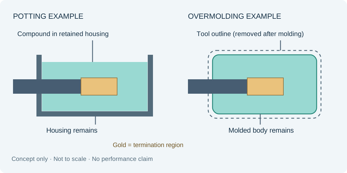
The drawings are simplified concepts, not production designs. Neither shows a validated seal or a complete strain-relief design. In both cases, the cable entry, termination location, material boundaries and required clearances must be defined.
A retained housing can provide the external mounting shape while the compound fills an internal region. A molded body can combine the outer geometry and encapsulation in one shape. Those observations are useful starting points, but neither construction automatically solves cable retention, shielding continuity or leakage at an interface.
Ask what the termination must survive during processing
Scroll sideways to read all columns.
| Design input | Potting review | Overmolding review |
|---|---|---|
| Material identity | Exact compound, components and applicable processing instructions | Exact molding grade and applicable processing instructions |
| Component exposure | Dispensing, cure conditions and compatibility of contacting materials | Process temperature, pressure and support of inserted components |
| Geometry control | Housing, fill boundary and areas that must remain clear | Cavity, insert location and areas excluded from molding |
| Internal condition | Agreed controls and evidence for fill and any prohibited voids | Agreed controls and evidence for fill and insert position |
| Cable exit | Retention and strain-relief arrangement | Exit geometry, jacket interface and strain-relief arrangement |
| Production change | Compound, housing and process changes | Material, tooling, insert and process changes |
Ask the responsible manufacturer to evaluate the actual parts rather than supply a generic assurance that the process is gentle. A contact, seal, jacket or component can impose its own constraints. The proposal should identify which constraints are supported and which still need testing.
Decide what must remain accessible
Specify whether maintenance requires replacing the whole assembly, opening a housing or reaching individual terminations. Do not treat potting as automatically repairable: removing a cured compound may damage the cable or components. Equally, do not assume every molded construction has the same disassembly behavior.
If field access is essential, compare a serviceable enclosure or another protection method before committing to encapsulation. Record the acceptable replacement unit and any diagnostic access needed. The service strategy affects the design independently of whether a sample initially passes electrical tests.
Fictional selection review for a sensor lead
EX-ENC-53 is an invented sensor lead with a small termination board. Option P retains a rectangular housing and pots the board region. Option M forms an external molded body around the supported board. The project requires a defined installation envelope and cable-exit direction, but no process has been approved.
Scroll sideways to read all columns.
| Requirement | Option P finding | Option M finding | Next decision |
|---|---|---|---|
| Installation envelope | Housing drawing fits the available space | Proposed body needs a revised mounting feature | Compare complete installed drawings |
| Process compatibility | Compound and cure exposure still pending | Board support and molding exposure still pending | Obtain component and process reviews for both |
| Cable retention | Separate entry feature proposed | Molded exit proposed | Agree mechanical verification of each construction |
| Service | Whole lead replacement is acceptable | Whole lead replacement is acceptable | Record this boundary; do not promise internal repair |
| Environmental target | No assembly evidence yet | No assembly evidence yet | Define the same required test scope before comparing results |
| Supply | Supplier scope unconfirmed | Supplier scope unconfirmed | Obtain explicit process and verification proposals |
The team keeps both options open until the missing evidence is available. It does not select M merely because its drawing has fewer visible parts, or P because it appears to avoid a shaped mold. A comparable quotation must include the housing or tooling, assembly operations and agreed verification for each option.
Approve the assembly, not the process label
Keep the released drawing, materials, internal arrangement and agreed evidence together. Include checks needed before the termination becomes inaccessible and checks required afterward. Define whether destructive inspection is part of the evaluation and how its samples will be identified.
A material data sheet supports material selection within its stated conditions. It does not assign an environmental rating to the completed lead. Apply the same rule to both candidate processes so the comparison stays focused on the product requirement.
Frequently asked questions
Is low-pressure molding the same as potting?
No. They can serve related protection needs, but the proposed process, material setting mechanism and shape control must be identified rather than inferred from the end use.
Which option is more repairable?
There is no universal answer. Review the exact compound, housing, access route and allowed damage. If internal repair is required, make it an explicit design requirement.
Does encapsulation guarantee waterproof performance?
No. The complete assembly and its interfaces need the agreed verification in the specified condition. Appearance and material claims alone do not establish that result.
Request a defined process proposal
For an overmolded cable project review, provide the termination layout, installation envelope, cable details and acceptance requirements. Contact Zeakka to identify an appropriate supplier review. Potting, low-pressure molding or another encapsulation route must be confirmed as a project-specific supply scope before quotation or commitment.
Share this article
Help others discover this content