
JST PA vs PH: Selecting Around the Board and Retention Requirements
Table of Contents
A request for a “2.0 mm JST cable” does not distinguish PA from PH. If the equipment already has a board connector, identify that part first. If the board is still being designed, compare complete component sets against the installation and retention requirements before choosing either family.
This comparison uses four-circuit, top-entry, through-hole examples. It does not propose inserting a PA cable housing into a PH header, or replacing either half independently. For a wider family overview, see common JST connector types.
Start with two documented component sets
Scroll sideways to read all columns.
| Review item | PA example | PH example |
|---|---|---|
| Cable housing | PAP-04V-S, standard type | PHR-4 |
| Board header | B04B-PASK, without boss | B4B-PH-K-S |
| Contact example | SPHD-002T-P0.5 | SPH-002T-P0.5S |
| Circuits and pitch | Four; 2.0 mm | Four; 2.0 mm |
| Header body length, catalog dimension B | 10.0 mm | 9.9 mm |
| Top-entry assembled height reference | 9.9 mm with standard housing | 8.0 mm |
| Selected contact wire range | AWG 28–24; insulation OD 0.76–1.5 mm | AWG 30–24; insulation OD 0.8–1.5 mm |
References: JST PA family catalog, pages 3, 6 and 9; JST PH catalog, pages 1–3. The names follow those catalog tables. Confirm the full ordering designation, applicable drawing and current availability before purchase. Dimensions summarize the indicated nominal/reference geometry; they omit tolerances and are not a manufacturing drawing.
The table keeps the PA standard housing separate from the retainer-compatible PA option. A retainer is not an accessory to add indiscriminately to PAP-04V-S. Changing to a retainer-compatible construction requires its specified housing, contact and retainer, plus another envelope review.
Define what the retention requirement must achieve
JST describes PA as having a secure locking mechanism. The project still needs to establish whether that mechanism can be engaged, inspected and released in the installed position. A latch hidden behind an enclosure wall can create a service problem even when the assembled connector fits.
Keep three questions separate: does the housing remain mated, does each contact remain seated in its housing, and is the cable supported so that service loads do not enter the termination? A positive housing latch does not resolve all three. Likewise, a successful hand mating check is not evidence that the assembly meets an application's vibration or repeated-service requirement.
Do not choose the family from an unsupported claim that one is “vibration proof.” Write down the relevant equipment conditions and required verification. The retention description identifies a feature to assess, not a completed qualification result.
Check installation and release space separately
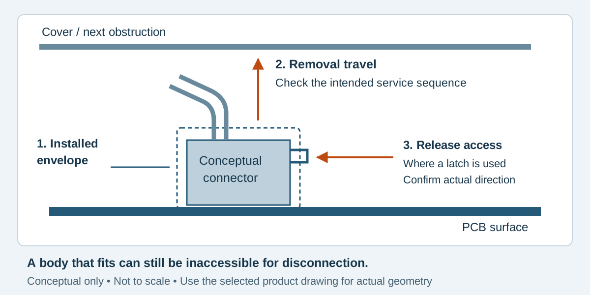
The sketch separates three spaces that are easily combined into a single height allowance. It is an original conceptual installation example, not a scaled representation of either connector or a source of clearance dimensions.
An enclosure can clear the installed housing but obstruct its removal. A cover may need to come off before disconnection; alternatively, the board may need to slide out. Establish the intended assembly and service sequence, then check that sequence with the selected parts and the actual wire exit.
For a release feature, confirm the access direction from the exact product drawing and handling instructions. Do not invent a fixed finger clearance or use a tool to force access without an approved method. Include the wire bundle and neighboring components in the review, rather than measuring an isolated connector model.
A fictional four-circuit decision
EX-PA-PH-56 is an invented control-board design with four required circuits and a removable top cover. Both board and cable may change at this stage. The team considers the two component sets above; neither has yet been released.
Scroll sideways to read all columns.
| Project observation | Review action | Decision that remains open |
|---|---|---|
| A low cover is close to the existing interface | Compare the complete mated drawings with enclosure tolerances | Whether the PA installation fits |
| Maintenance removes the cover before disconnecting the cable | Review removal travel with the cover removed | Whether surrounding parts still obstruct handling |
| The requirement calls for an accessible housing release | Locate and demonstrate the selected mechanism | Whether the proposed interface meets the service requirement |
| Wire has already been specified | Check actual conductor and insulation dimensions against the exact contact | Whether either contact needs to change |
| A cable tie point is available nearby | Review routing and support with the assembled harness | Whether the cable loads the connection during service |
The useful output is a reviewed component set and a documented installation sequence. It is not a winner based on the smaller catalog height. If the board were already frozen with a PH header, the PA proposal would instead be an interface change affecting both the board and cable.
Freeze the cable specification with the interface
Record housing, contact, board mate and wire references in the same review. Add cavity assignments, the defined connector view, cable length datums, support points and any sample-verification requirements. Preserve manufacturer identity: an alternative offered against a JST reference needs its own supporting evidence.
Do not copy the PH crimp setup to PA merely because the selected wire lies within both listed ranges. The contact and applicable tooling instructions determine the termination process. Confirm those details with the responsible supplier before approving the sample.
PA and PH questions
Does the common 2.0 mm pitch make PA and PH interchangeable?
No. Contact spacing does not establish the mating geometry, contact system or retention arrangement. Review the complete specified pair.
Can a retainer be fitted to every PA housing?
No. The PA catalog distinguishes standard and retainer-compatible constructions. Select the documented parts for the intended configuration.
Should PA replace PH whenever retention matters?
That is a project decision, not a general upgrade rule. Check the required behavior, access, complete interface and verification conditions before changing either side.
Request a review of the complete PA or PH assembly
For custom JST cable assemblies, send the board-mate reference, selected housing and contact, wire specification and enclosure constraints. Contact Zeakka with the proposed installation and service sequence. Zeakka coordinates sourcing and supplier review; original-part use and alternative proposals must be identified separately and confirmed for the project.
Share this article
Help others discover this content