
Cable Assemblies for Equipment Manufacturers
Table of Contents
An equipment cable has to fit more than its mating connector. It must reach the intended interface, follow the available route, allow installation in the right sequence and remain identifiable when a service replacement is needed.
Zeakka coordinates sourcing for discrete-wire, flat-ribbon and overmolded cable assemblies. We are a trading and sourcing partner, not the factory or the equipment design authority. Share your equipment-side interfaces and constraints so the cable quotation and sample plan can address the actual installation.
Send an equipment cable package for review. A sketch or written requirement can start the discussion; the agreed configuration and validation responsibilities are established before the build is released.
Organize the enquiry around connection points
Assign a clear identifier to each connection in the equipment. Identify the exact mates, required circuits and relevant board, panel or module revisions. Then connect those interface records to individual cable assembly numbers.
Include the connector view and cavity numbering used in the connection list. State whether the cable is installed before or after a module enters the enclosure. A finished cable that passes through an opening during assembly may have a different installation constraint from one connected after both modules are fixed.
List the relevant operating and handling conditions, but distinguish a requirement from a proven result. If temperature, motion, cleaning exposure or an enclosure sealing requirement affects the cable, provide the actual project conditions and acceptance basis for supplier review. A drawing note alone does not establish that the proposed configuration has met them.
Select among three assembly paths
Scroll sideways to read all columns.
| Construction to review | Equipment inputs that matter | Dedicated supply page |
|---|---|---|
| Discrete wire | Individual circuits, branches, labels, connector access and protection | Discrete-wire assemblies |
| Flat ribbon / IDC | Conductor count, pin-one orientation, folds, breakouts and board spacing | Flat-ribbon assemblies |
| Overmolded | Molded envelope, cable exit, mating clearance, material interface and tooling | Overmolded assemblies |
A branched connection, a molded termination and protective sleeving describe different configuration dimensions. They are not mutually exclusive categories. Identify the connections first, then the construction and protection needed for each part of the route.
The selected process and supplier scope require review. A request for potting, special shielding performance or an environmental rating is not automatically included because the project contains an overmolded cable.
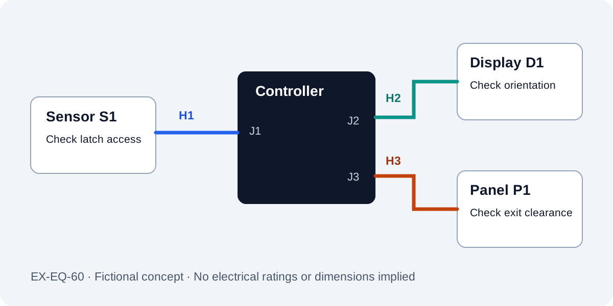
A fictional equipment connection map
The following map describes invented equipment EX-EQ-60. It is a planning illustration, not a customer drawing, approved design or scaled installation layout. No operating rating is assigned.
Scroll sideways to read all columns.
| Cable | Connection purpose | Installation question | Evidence owner in the example |
|---|---|---|---|
| EX-H1 | Sensor module S1 to controller J1 | Can the latch be accessed after the controller is fitted? | Equipment engineer checks installed access |
| EX-H2 | Controller J2 to display D1 | Does pin-one orientation remain unambiguous after the agreed ribbon fold? | Design owner approves the map; assembly team checks routing |
| EX-H3 | Controller J3 to panel connection P1 | Does the proposed molded exit clear the bracket and leave the mating envelope free? | Equipment engineer approves geometry; supplier reviews mold feasibility |
The buyer proposes 40 equipment builds, each using one of each cable: 40 H1, 40 H2 and 40 H3 assemblies. Sample quantities are specified separately for the checks above. A three-cable equipment set does not mean a single 40-piece cable order, and the proposed production quantity is not evidence of material availability.
In this fictional review, H1's latch is inaccessible with the initial mounting sequence. The equipment engineer changes the installation sequence and requests another sample fit check; purchasing does not simply accept the cable because its electrical map is correct. H2 and H3 retain their own unresolved questions and approval records.
Give installation dimensions a common basis
Define the length endpoints and critical datums. Provide the available routing corridor, panel thickness or bracket reference where relevant, as well as any service loop requirement. Identify which dimensions are fixed by the equipment and which are proposals for review.
Do not use a generic bend-radius ratio to settle an unidentified cable route. Give the actual cable construction and applicable guidance to the responsible reviewer. Similarly, a cable-exit direction must be considered together with the connector latch, mating access and space needed to install or remove it.
The length-tolerance guide explains how datums affect a reproducible measurement. The equipment enquiry should add the surrounding installation information that a standalone cable drawing may omit.
Separate factory checks from equipment validation
Every finished cable assembly receives continuity and short-circuit testing, with pull-force testing sampled for the project. Agree the particular records and additional checks in the quotation scope. These checks do not replace fitting the identified sample into the equipment or reviewing the required application performance.
Name the equipment reviewer and the configuration used for validation. Record cable revision, mating modules, equipment revision and the conditions of the check. If a sample fits an open chassis, decide whether the closed enclosure, assembly sequence or service operation introduces other relevant requirements.
Use the sample approval checklist to record what was evaluated and the scope of any approval. When a sample needs changes, return the issue with its references rather than asking the supplier to make the cable “more flexible” or “a little shorter” without an agreed definition.
Plan the service replacement alongside production
Decide whether maintenance replaces an individual cable, a branch assembly or a kit. Record the relevant part and revision identifiers in the service information. Different lengths or mappings need distinguishable identities even if their connectors look alike.
Identify access to latches and fasteners, the removal sequence and any items affected by replacing the cable. If a replacement requires opening a sealed or permanently assembled region, include that consequence in the equipment design review. This page does not promise field repairability for every construction.
For repeat orders, provide the approved configuration and identify changes in the equipment. Review old inventory and service compatibility separately when a new production revision is proposed. New equipment release does not automatically make an earlier replacement cable suitable or obsolete.
What the documented Swiss project demonstrates
The Swiss ohmic flow heater case began with a written enquiry covering four cable concepts without drawings or images. Zeakka clarified requirements and material options. The final order covered three assemblies: 5,000 of one type and 1,000 each of two others.
That record supports the value of making written requirements reviewable. Its temperature, diameter, material and marking discussion belongs to that specific project. It does not establish a general temperature capability, equipment performance claim or certification for other assemblies. The fictional EX-EQ-60 map above is unrelated to that customer.
Equipment sourcing questions
Can the first enquiry use a sketch instead of a finished drawing?
Yes. Send identified interfaces, a connection list, available dimensions and the intended application. Zeakka can coordinate questions needed to establish the sample and quotation basis.
Can one project combine the three cable constructions?
Yes, the requirements can be reviewed together. Each item still needs its own confirmed scope, suitable supplier and approval record; not every requested configuration is automatically feasible.
Does a tested cable mean the equipment installation is approved?
No. Cable checks and equipment validation have different scopes. The customer approves the final application and records the applicable equipment configuration.
Send the interfaces, routes and release needs together
Contact Zeakka with the cable list, equipment-side references, sketches or drawings, sample objectives and production quantities. Add any mandatory material or document requirements. We coordinate supplier review and quotations around the confirmed scope, while your team retains equipment design and application approval.
Share this article
Help others discover this content