
Molex PicoBlade vs Pico-Lock: Pitch, Profile and Retention
Table of Contents
PicoBlade and Pico-Lock are separate Molex connector systems. For a board that already exists, identify its header before ordering a cable. For a new board, compare the exact mated assembly, release access and wire termination rather than choosing from a family name or a headline current.
There is an important naming trap: Pico-Lock is not one pitch. Molex's current family includes 1.00, 1.50, 2.00 and 3.00 mm versions. This guide compares a 1.25 mm PicoBlade arrangement with the 1.50 mm Pico-Lock 504051/504050 arrangement. Its conclusions about dimensions and contacts do not describe every Pico-Lock version. Molex Pico-Lock family overview.
Start with two defined configurations
These are original Molex catalog examples, not specifications for Zeakka alternatives or an assembled cable. Both examples below use four circuits and a right-angle SMT header so the stated heights refer to comparable orientations.
Scroll sideways to read all columns.
| Selection input | PicoBlade example | Pico-Lock 1.50 mm example |
|---|---|---|
| Receptacle housing | 51021-0400 | 504051-0401 |
| Right-angle SMT header | 53261-0471 | 504050-0491 |
| Mating pitch | 1.25 mm | 1.50 mm |
| Listed mated height for this header | 3.40 mm | 2.00 mm |
| Retention arrangement | 51021 friction-lock housing | 504051 positive-lock housing |
| Contact examples | 50058-8000 or 50079-8000 | 504052-0098 or 504052-0298 |
The PicoBlade header page and Pico-Lock header page identify these exact heights and orientations. Housing descriptions are in the 51021 and 504051 series charts.
A lower height in this comparison does not establish a smaller footprint or a drop-in replacement. The pitch, mounting pattern and cable-side construction differ. Compare the full drawings, including PCB pads, keep-out space and wire exit. Replacing an installed PicoBlade connection with Pico-Lock is a design change, not a cable-only substitution justified by both products being miniature.
A low profile still needs a usable release path
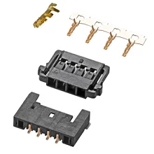
Pico-Lock alternative catalog components. The photograph does not identify the exact pitch, height or original part numbers used in the comparison. View Pico-Lock alternatives.
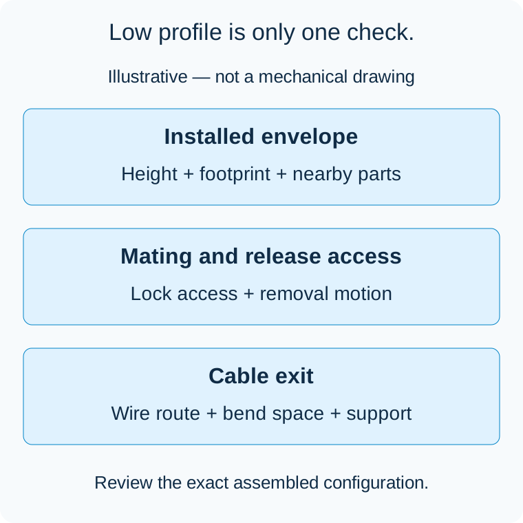
Illustrative space-review diagram, not connector geometry or an official mechanical drawing. No dimensions or cross-mating are implied.
The 1.50 mm Pico-Lock construction combines a low profile with a positive-lock arrangement. Its side locks deserve attention when nearby components, enclosure walls or cable channels limit access. A design that fits under a cover can still be difficult to disconnect without loading the wires.
For the PicoBlade option, evaluate the specified friction-lock arrangement and the permitted removal method. Do not translate the difference in lock names into a universal vibration or retention ranking. The application, actual mating parts and cable loading still determine the evidence needed.
Review three spaces separately: the installed connector envelope, the motion required to mate and release it, and the cable's route after it leaves the housing. A nominal height covers only part of that problem. Check the assembled product rather than assuming access from an unobstructed bench sample will exist in the enclosure.
Choose the terminal before finalizing the wire
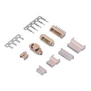
PicoBlade alternative catalog components. Shown for identification only; original catalog ratings do not rate these pictured alternatives. View PicoBlade alternatives.
A series-level wire range can hide two different contacts. The current Molex part pages give these examples:
Scroll sideways to read all columns.
| Exact crimp contact | Listed conductor range | Listed insulation diameter |
|---|---|---|
| PicoBlade 50058-8000 | AWG 32–28 | 0.50–1.00 mm |
| PicoBlade 50079-8000 | AWG 28–26 | 0.50–1.04 mm |
| Pico-Lock 504052-0098 | AWG 28–24 | 0.80–1.15 mm |
| Pico-Lock 504052-0298 | AWG 30 or 32 | 0.54–0.80 mm |
Sources: 50058-8000, 50079-8000, 504052-0098 and 504052-0298.
These ranges are not interchangeable tooling settings. Retain the actual wire specification, conductor construction and insulation diameter with the contact reference. A thinner jacket or a different strand construction needs review even when the AWG label stays the same. The relevant application and crimp specifications must govern the selected combination.
Read current figures with their conditions
The cited PicoBlade header lists a 1.0 A maximum per contact; the cited four-circuit Pico-Lock header lists 3.0 A. Those entries alone do not approve the proposed cable's operating current.
The Pico-Lock datasheet, page 3 shows why configuration matters: its 1.50 mm reference table lists 3.0 A for four circuits with AWG 24, but 2.5 A for four circuits with AWG 26. The notes specify all circuits powered, temperature rise measured at the crimp barrel and the influence of PCB trace design. The table is reference information, not a finished-product qualification.
Also reconcile the selected component's own limit: the 504052-0298 part page lists a 1.0 A maximum, so a broader family table must not be used to silently raise that contact's rating. Obtain the current applicable product specification and resolve any discrepancy for the exact parts before design approval.
Review wire heating, voltage drop, ambient temperature and circuit loading together. The wire-gauge selection guide explains why meeting a voltage-drop target alone does not establish thermal suitability. Do not multiply a catalog maximum by the number of positions to claim total cable power.
Match the choice to the board and service requirement
Existing PicoBlade board: preserve the documented matching interface and determine the cable's exact contact and wire requirements. Changing families usually introduces PCB and mechanical work beyond the cable order.
New design with a tight height limit: investigate the defined Pico-Lock option using its actual mated drawing, release access and wire route. Confirm the electrical configuration independently; a low profile is not an electrical rating.
Alternative-component request: distinguish the original reference from the proposed supplier's part. Browse PicoBlade alternatives or Pico-Lock alternatives, then use the alternative verification guide to review the exact combination.
Zeakka is a trading and sourcing partner. Original Molex components may be considered for finished cable assemblies according to exact part selection and availability; original components are not sold separately. Send the installed header or proposed board interface, required circuits and wire specification so the sourcing review starts with the correct Pico-Lock variant or PicoBlade combination.
Related selection guides
JST GH vs Molex PicoBlade: Choosing Between Two 1.25 mm Systems · Common Molex Connector Types Compared: PicoBlade, Pico-Lock, Pico-SPOX, Micro-Fit, Mini-Fit Jr. and Mega-Fit
Share this article
Help others discover this content