
Common Molex Connector Types Compared: PicoBlade, Pico-Lock, Pico-SPOX, Micro-Fit, Mini-Fit Jr. and Mega-Fit
Table of Contents
A Molex family name narrows the search; it does not finish the cable specification. These six families cover different connection sizes, retention arrangements and integration choices. Use this guide to choose which exact drawings and component combinations to investigate, rather than treating the families as a ladder from “small” to “powerful.”
If a board or device already exists, begin with its mating-part reference. If the interface is still open, begin with the connection layout, available space, circuit loading and service requirements. A proposed change of family can affect the board and enclosure as well as the cable.
Six families as selection starting points
This table summarizes original Molex families and examples. It does not assign original specifications to Zeakka alternative components or approve a finished assembly. Pitch is contact spacing, not overall connector size.
Scroll sideways to read all columns.
| Family | Pitch scope | A useful reason to investigate it | A detail that must not be assumed |
|---|---|---|---|
| PicoBlade | 1.25 mm | Compact connections, including an existing board using a documented PicoBlade interface | A generic “1.25 mm” cable is not an identified mating part |
| Pico-Lock | 1.00, 1.50, 2.00 and 3.00 mm variants | A low-profile connection with the specified locking arrangement | One variant's height, wire range or current does not describe all Pico-Lock versions |
| Pico-SPOX | 1.50 mm | A compact wire-to-board interface with friction locking | The exact housing, terminal and header still define the connection |
| Micro-Fit | 3.00 mm family | Compact power/signal layouts with several connection and integration options | A feature on BMI, TPA or another variant is not automatically present on every Micro-Fit part |
| Mini-Fit Jr. | 4.20 mm | An established Jr. interface or a power connection meeting its exact component limits | Classic Jr. contacts must not inherit Mini-Fit Plus HCS ratings |
| Mega-Fit | 5.70 mm | A power interface needing investigation beyond the existing smaller connection | A family maximum is not a current rating for every housing, contact or cable |
Original references: PicoBlade 51021 housing series, Pico-Lock, Pico-SPOX, Micro-Fit, Mini-Fit and Mega-Fit.
Catalog examples from the alternative range
Zeakka catalog examples of alternatives. Images are not to scale; specifications depend on the quoted parts.
Scroll sideways to read all columns.
| Compact interface examples | Power interface examples |
|---|---|
PicoBlade alternatives 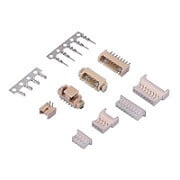 | Micro-Fit alternatives 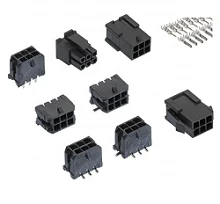 |
Pico-Lock alternatives 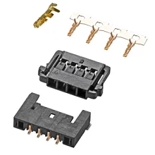 | Mini-Fit family alternatives 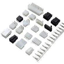 |
Pico-SPOX alternatives 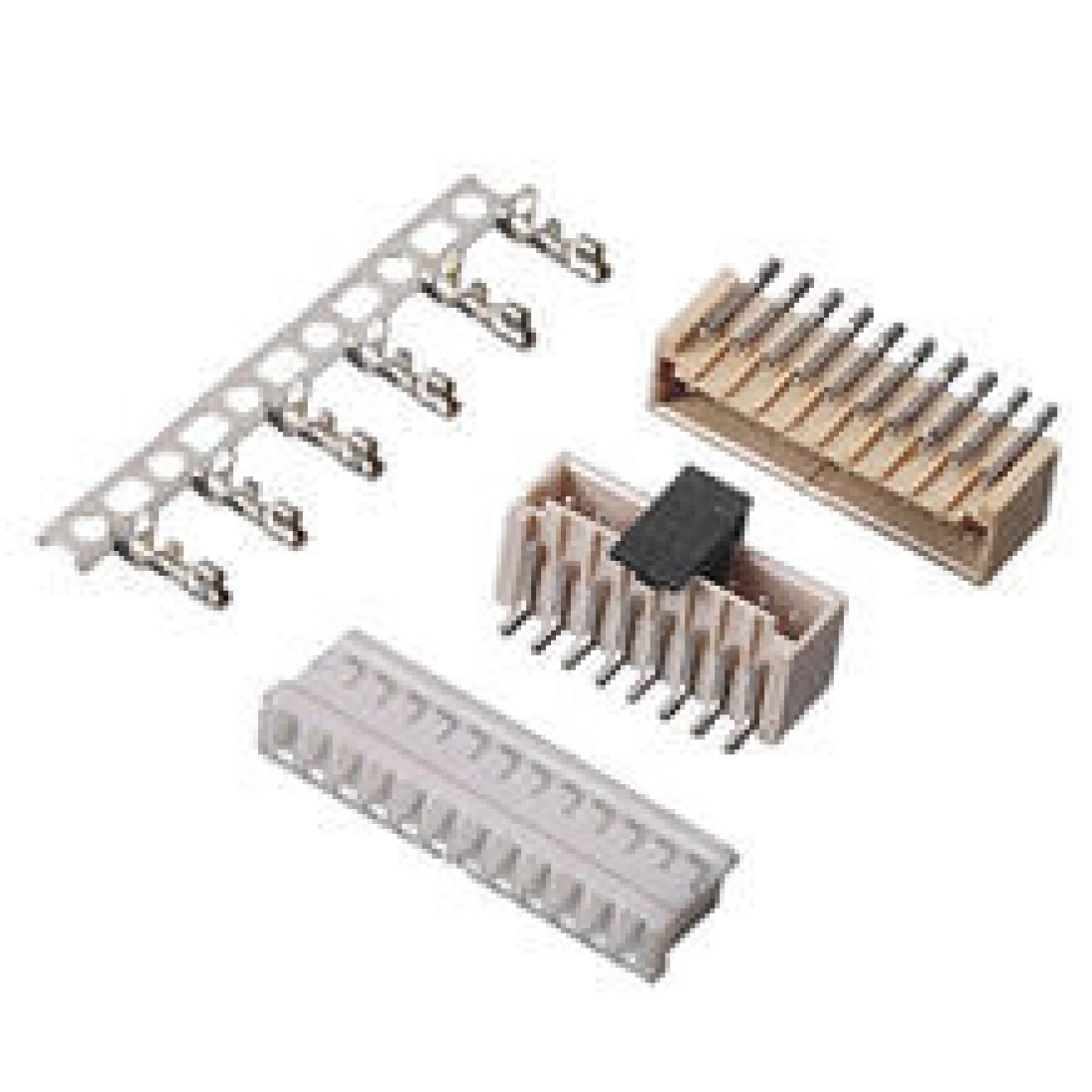 | Mega-Fit alternatives 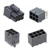 |
Start with the interface that can actually change
An installed header fixes an important boundary. A smaller housing from another family does not create a compatible cable, even if the circuit count is the same. Identify the equipment-side part and its permitted cable-side counterpart before optimizing wire routing or sourcing alternatives.
For a new board, separate interface selection from physical layout. A wire-to-board connection terminates at a PCB component; a wire-to-wire disconnect divides a cable path. A family with multiple configurations still requires the correct components for the chosen layout. “Micro-Fit cable,” for example, is not enough to distinguish the mating hardware at each end.
Write down which parts are fixed and which can change. That prevents a purchasing request from quietly turning into a PCB redesign. If both sides may change, compare complete proposed configurations under the same requirements instead of pairing one family's housing with another family's header.
Use space and service access together
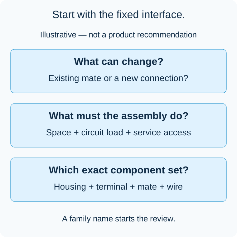
Illustrative decision sequence, not connector geometry, a size comparison or a product recommendation.
For PicoBlade, Pico-Lock and Pico-SPOX, small dimensions make it particularly important to check the actual assembly envelope. Measure the available installed space, but also allow for mating motion, latch access and the cable's exit path. A low-profile connector may solve a height constraint while leaving another clearance unresolved.
The same reasoning applies to the larger interfaces. Moving to a different wire or terminal can change the cable's stiffness and the room needed for bends. A connector body that fits does not prove the completed harness can be installed or serviced without loading the contacts.
Compare like orientations. A vertical-header height and a right-angle-header height answer different layout questions. Use the exact mated drawings and board footprint rather than ranking families from photographs or pitch alone. For the specific compact-power tradeoff, see the Micro-Fit 3.0 vs Mini-Fit Jr. guide.
Avoid a single current-ranking chart
A useful current comparison needs a defined terminal, wire, circuit loading and thermal condition. Family headline figures often describe different configurations. Sorting them numerically can make a larger number appear to be an unconditional upgrade.
Mini-Fit Jr. is a clear example: the classic terminal tables and the broader Mini-Fit family options are not one interchangeable rating. Pico-Lock is another: four pitch variants cannot be reduced to one wire range or one allowable current. Keep the variant and exact contact attached to every value used in a decision.
Check the whole power path, including other connectors, wire length, board traces and loaded adjacent circuits. Replacing one interface does not increase the limits of the parts left in place. The wire-gauge and connector-limits guide explains the separate roles of voltage drop, heating and termination fit.
Once the candidate is identified, use its product specification and applicable derating information to establish the configuration-specific current limit. If a product page and a family summary appear inconsistent, resolve that discrepancy before approval rather than choosing the larger number.
Move from a family to a reviewable component set
Before requesting a sample, identify the housing, contact and mating-part references, circuit count and any special variant. Add the wire specification and the required electrical mapping. A familiar family name does not define Pin 1, signal assignment or polarity.
Separate manufacturer identity from interface description. An alternative offered against a Molex reference needs its own dimensional, material and performance evidence; the original catalog cannot serve as its qualification record. Use the connector-alternative verification guide to identify the evidence needed before accepting a proposed substitute.
For replacement and long-life products, check lifecycle and availability against the exact orderable parts before freezing the BOM. Do not infer current supply from a family page or treat one part's lifecycle status as applying to an entire family.
Find the appropriate sourcing page
The following Zeakka pages describe alternative-component options and provide a starting point for a project discussion:
- PicoBlade alternatives and Pico-Lock alternatives.
- Pico-SPOX alternatives.
- Micro-Fit 3.0 alternatives and Mini-Fit family alternatives.
- Mega-Fit alternatives.
Zeakka is a trading and sourcing partner. Original Molex components can be considered within finished cable assemblies according to exact part selection and availability; original components are not sold separately. An alternative proposal remains separately identified and reviewed. Contact Zeakka with the fixed mating interface and the constraints driving the selection, so the next step is a specific component and cable review rather than a generic family recommendation.
Related selection guides
Molex PicoBlade vs Pico-Lock: Pitch, Profile and Retention · Molex Mini-Fit Jr. vs Mega-Fit: Choosing a Power Cable Interface
Share this article
Help others discover this content