
Ribbon Cable Breakouts: Specifying the Separated Ends
Table of Contents
A ribbon cable breakout separates selected conductors or conductor groups so they can reach individual destinations. The downstream ends may use crimp contacts, specified prepared wire ends or another approved termination. The ribbon's original IDC interface does not define those ends automatically.
Specify the transition as part of one controlled assembly: the cable permitted to separate, the location where separation begins, the resulting lead lengths and every conductor destination. A sketch that merely fans six lines outward leaves important manufacturing and inspection decisions open.
Define the separation boundary and every endpoint
Fictional EX-BR-03: C1–C3 terminate at P1 and C4–C6 at P2. The sketch does not qualify a cable for separation or a terminal for the resulting lead.
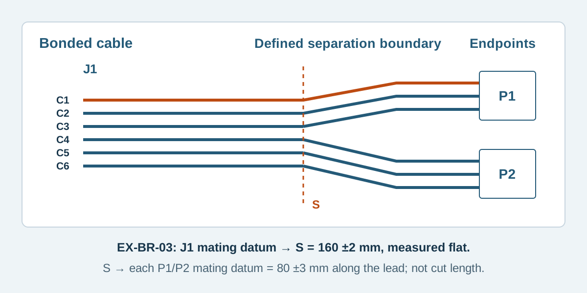
Conceptual illustration. Fictional examples are not approved product configurations, tooling instructions or inspection results.
Confirm that the actual cable permits the proposed separation
Not every flat interconnect is a separable ribbon cable. An FFC construction, a shielded or jacketed flat cable and a ribbon with bonded round conductors need different handling and termination review. Identify the exact cable before using words such as “split,” “peel” or “zip.”
For a specific example, the 3M 3365 technical sheet, TS-0080-B, describes its 28 AWG stranded construction as zippable for branching or discrete termination. That statement belongs to that product. It does not establish a separation method, allowable damage or downstream contact compatibility for another cable.
Ask for the applicable preparation instructions and review the separated insulation and conductors against the selected construction's criteria. Do not use a knife depth or separation force borrowed from a photograph. Any proposed reinforcement at the transition also needs a material, position and application definition.
The IDC versus crimp guide covers the earlier choice of termination approach. This article addresses the transition after a mixed construction has been proposed.
Mark where the ribbon stops and the breakout begins
Define a transverse separation boundary and a measurement datum at the ribbon connector. State the assembly condition in which the dimension is checked. A free, flat assembly and a cable routed around a bracket are different measurement references.
Then dimension each outgoing group or lead from the separation boundary to its defined downstream datum. A dimension to a connector's mating face differs from a raw conductor cut length or the length of exposed copper. Keep those references distinct.
Scroll sideways to read all columns.
| Drawing item | Definition needed | Common ambiguity to remove |
|---|---|---|
| Main ribbon length | Named connector datum to separation boundary | Does the length include the connector body? |
| Separation extent | Which conductor webs are separated, and where | Are conductors fully individual or retained in groups? |
| Outgoing lead length | Boundary to named termination datum, measured along the specified path | Is a straight-line reach being confused with lead length? |
| End preparation | Applicable contact or defined prepared-end condition | Does “bare end” mean stripped, untreated or simply no connector? |
| Transition protection | Material, coverage and restraint if required | Is unspecified tape being treated as an approved strain relief? |
Do not assign a universal bend radius or protection method to the separated region. Evaluate its installed route, nearby edges and loads with the actual cable and equipment.
Keep a complete conductor-to-end table
The fictional example EX-BR-03 has six continuous conductors, C1 through C6. J1 is a conceptual ribbon connector; P1 and P2 are conceptual three-position downstream connectors. The labels do not reproduce a commercial contact layout, identify orderable parts or approve a construction.
Scroll sideways to read all columns.
| Conductor | Ribbon-end contact | Downstream contact | Required relationship |
|---|---|---|---|
| C1 | J1.1 | P1.1 | One continuous conductor |
| C2 | J1.2 | P1.2 | One continuous conductor |
| C3 | J1.3 | P1.3 | One continuous conductor |
| C4 | J1.4 | P2.1 | One continuous conductor |
| C5 | J1.5 | P2.2 | One continuous conductor |
| C6 | J1.6 | P2.3 | One continuous conductor |
All six rows are required. Different rows remain electrically separate; the example has no splices, shared returns or unused conductors. P1 receives C1–C3 and P2 receives C4–C6. Add explicit views for each real connector and its cavity numbering when selecting the actual parts.
In this example, the proposed flat dimension from J1's named mating-face datum to the separation boundary is 160 ± 2 mm. Each outgoing lead is 80 ± 3 mm, measured along its centerline from that boundary to the applicable P1 or P2 mating-face datum. These fictional values illustrate separate controlled dimensions. They are not raw cut lengths, and no independent overall tolerance is specified.
Routing the groups apart does not change the table. Reassigning a conductor to another contact does, and requires a revised drawing and test definition.
Check the downstream contact against the separated wire
An IDC cable's conductor size alone does not approve a crimp contact. Review conductor construction, insulation profile and dimensions, preparation and tooling for the actual separated conductor. Cable pitch or overall ribbon thickness must not be silently substituted for an individual wire's insulation outside diameter.
For comparison, the JST XH catalog lists SXH-002T-P0.6 for AWG 30–26 with insulation outside diameter 0.9–1.3 mm. That is a documented selection boundary, not proof that a separated 28 AWG ribbon conductor fits it. Establish the relevant insulation geometry and obtain applicability confirmation rather than approving the contact from AWG alone.
If a suitable direct termination cannot be established, treat another construction as a new proposal. Adding a splice or changing to discrete wires introduces its own parts, dimensions, protection and verification. Show that change rather than hiding it beneath a generic breakout label.
Inspect the transition and test the full map
Record the approved cable, separation location, prepared ends and destination references with the assembly revision. Review accessible insulation condition at the transition and along the separated leads using the applicable criteria. A clean appearance does not establish a hidden termination's performance.
The connection test definition must cover every required contact in the table and unintended connections between nets. Include all downstream ends in the fixture mapping. A passing test only at J1 cannot establish connections at P1 and P2.
Keep the physical and electrical results separate. See the IDC inspection guide for evidence boundaries and the ribbon specification worksheet for the broader assembly record.
Breakout questions
Can any ribbon cable be separated into individual wires?
No. Confirm the exact cable construction and its permitted preparation. A manufacturer's zippable-cable statement does not apply automatically to another ribbon, FFC or shielded construction.
Does 28 AWG guarantee compatibility with a 28 AWG crimp contact?
No. Conductor construction, insulation dimensions and profile, contact applicability and tooling still need review. The ribbon's outer dimensions are not a substitute for the separated conductor's relevant dimensions.
Can the breakout length be specified as one overall number?
That leaves the separation boundary and individual reach uncertain. Define the main section and outgoing lengths from explicit datums, with their measurement conditions and controlling tolerances.
Send the transition definition with the quotation request
For custom flat ribbon cable assemblies, send the exact cable reference, complete mapping, separation boundary, outgoing lengths and downstream component requirements. Zeakka is a trading and sourcing coordinator; cable preparation, termination feasibility and inspection arrangements require supplier review for the project. Contact Zeakka with the drawing and mark unresolved contact compatibility clearly.
Share this article
Help others discover this content