
Stripped, Retained-Insulation and Tinned Wire Ends: Define the Finish
Table of Contents
A request for a cable with “bare ends” can describe several different deliveries: insulation removed to expose the strands, a cut insulation slug left in place for later removal, or conductors coated with solder. Those conditions are not interchangeable at the receiving connection.
Name the required condition at each wire end and dimension it from explicit references. Then check the receiving terminal, solder connection or later manufacturing operation. A neat prepared end is useful only when it is suitable for that next step.
Describe the delivered wire-end condition explicitly
Conceptual end conditions without universal dimensions. The selected receiving terminal determines whether solder-tinned ends are permitted.
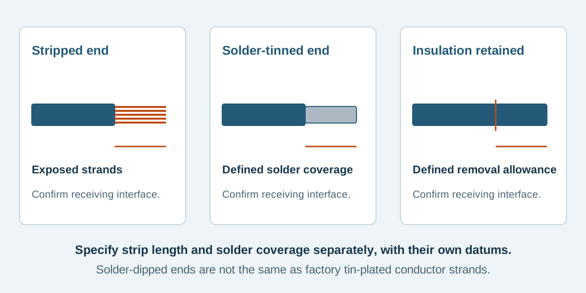
Conceptual illustration. Fictional examples are not approved product configurations, tooling instructions or inspection results.
Distinguish the three delivery conditions
For this article, the following definitions make the request reviewable. Confirm the supplier uses the same meaning rather than relying on a local shorthand.
Scroll sideways to read all columns.
| End condition | Delivery definition | Decision still needed |
|---|---|---|
| Stripped, untreated end | Specified insulation length removed; strands exposed without added solder | Receiving interface, conductor condition and exposed length |
| Retained insulation slug | Insulation cut at a defined distance from the tip, with the cut section left in place | Slug position, removal by the next operation and protection during delivery |
| Solder-tinned end | Solder intentionally applied to the prepared conductor end | Whether the interface permits it, controlled coverage and applicable process requirements |
A retained slug is not a permanent insulating termination or a ready-to-connect contact. State whether it remains fully seated or in another explicitly defined position. Do not write “partially stripped” when the intended position and exposed region are unknown.
“Untreated” here means no solder added during end preparation. It does not mean the purchased conductor must be unplated copper. Specify the underlying wire separately.
Keep conductor plating separate from end tinning
Wire can be manufactured using tinned copper strands. For example, the 3M 3365 technical sheet identifies tinned stranded copper in its conductor construction. That material description does not establish that the finished cable's stripped ends have been solder-dipped.
Applying solder to a prepared end is an additional operation. Do not add it to the order simply because the wire specification contains the word “tinned.” Conversely, specifying an untreated stripped end should not silently change the wire from its approved plated construction to another material.
Put the wire reference in the BOM and the end preparation in its own drawing note. This keeps material procurement and the downstream finishing operation independently identifiable.
Dimension the actual end condition
Define the conductor cut tip as one datum and the insulation cut or edge as another. State the exposed length or slug length, as appropriate. If solder tinning is required, define its allowed region separately instead of assuming it must cover every exposed millimeter.
A prepared-end drawing also needs the overall lead-length datum. A length measured to the conductor tip is different from one measured to an insulation edge or a later installed contact. Do not lose that distinction when changing the preparation.
The following dimensions are fictional teaching values for EX-END-05. They are not recommended settings or acceptance limits for a real wire or terminal.
Scroll sideways to read all columns.
| Example end | Fictional preparation | What the drawing must keep clear |
|---|---|---|
| A: stripped, untreated | Exposed conductor E = 5.0 ± 0.5 mm | No solder added; length measured from final insulation edge to conductor tip |
| B: retained slug | Cut position S = 5.0 ± 0.5 mm from conductor tip; slug fully seated | No intentionally exposed conductor before slug removal; next operation removes it |
| C: solder-tinned | Exposed region E = 5.0 ± 0.5 mm; allowed soldered length T = 4.0 ± 0.5 mm from tip | Soldered region stays within the exposed region; permitted process and boundary require review |
For end C, the maximum T is 4.5 mm and the minimum E is 4.5 mm, so the stated regions do not intentionally overlap the insulation. This geometric check does not prove that solder has not wicked beneath insulation, define an acceptable solder profile or approve the process. Those requirements need a separate applicable reference.
Let the receiving interface control the preparation
Obtain the exact terminal or connector instructions before selecting the end finish. Check permitted conductor construction, size, preparation length and any restrictions on ferrules or soldered ends. A product accepting stranded wire does not automatically accept every treatment applied to those strands.
For screw-style terminal blocks, Phoenix Contact's technical note explains how solder-dipped wire ends can become loose and how added material can affect fit. Do not assume tinning is a universal improvement for clamped connections. Follow the actual receiving product's requirements.
A ferrule is another specifically selected termination, not a synonym for a solder-tinned end. Use the ferrule specification guide when that is the proposed interface. Its sleeve length, wire applicability, crimp shape and receiving terminal still need agreement.
For a later crimp operation, follow the selected contact's preparation instructions rather than adding solder for strand control. JST's handling precautions, under precautions for crimping, direct users to the relevant connector and tooling manuals and require compatibility review for the chosen wire. A general end-finish note does not override that review.
For a solder connection, identify the actual receiving joint and applicable process requirements. The crimp versus solder guide discusses that process choice. This article defines the supplied end condition, not a universal soldering recipe.
Inspect and protect the prepared ends
Agree the inspection stage before packaging. Review exposed conductor condition, insulation condition, length and strand containment against the applicable criteria. A retained slug can obscure the prepared region; document what is checked before it is delivered and what the next operation must confirm after removal.
Where solder is specified, identify the evidence required for coverage, profile and the transition near the insulation. Do not declare a soldered end acceptable solely because it is shiny or passes continuity. Dimensional compliance and appearance do not answer every process question.
Specify packaging that preserves the approved condition through shipping and handling. Prevent unintended contact between exposed ends where necessary for the supplied assembly, and identify how any temporary protection is removed. Packaging is not permission to skip preparation inspection.
Keep different end conditions clearly associated with their wire and end identifiers. A bundle containing both untreated and tinned ends needs a schedule, not a single “all wires prepared” note.
Prepared-end questions
Is tinned copper wire the same as a solder-tinned end?
No. One describes the purchased conductor construction; the other describes a preparation operation at the end. Record both separately so an order cannot confuse them.
Are tinned ends suitable for every screw terminal?
Do not assume so. The receiving product's instructions determine the permitted preparation. Phoenix Contact's note identifies specific reasons solder-dipped ends can create loose or poorly fitting clamped connections.
Why leave an insulation slug on the wire?
It can be a specified delivery condition for removal at a later operation. Define the cut position, retained position and responsible next step; do not treat the slug as a finished permanent insulating component.
Send the receiving-interface requirements with the drawing
Contact Zeakka with the wire specification, end-by-end preparation schedule, explicit dimensions and receiving component documents. Identify whether the downstream work is performed by your team or included in the proposed assembly. Zeakka coordinates sourcing as a trading partner; stripping, slug retention, solder tinning and requested inspection arrangements all require project-specific feasibility confirmation.
Share this article
Help others discover this content