
Cable Overmolding Process: 7 Steps and Quality Checks
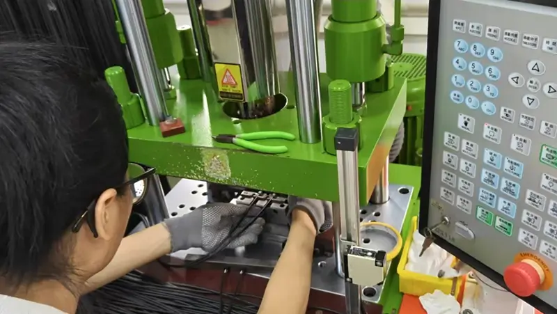
Table of Contents
What is cable overmolding?
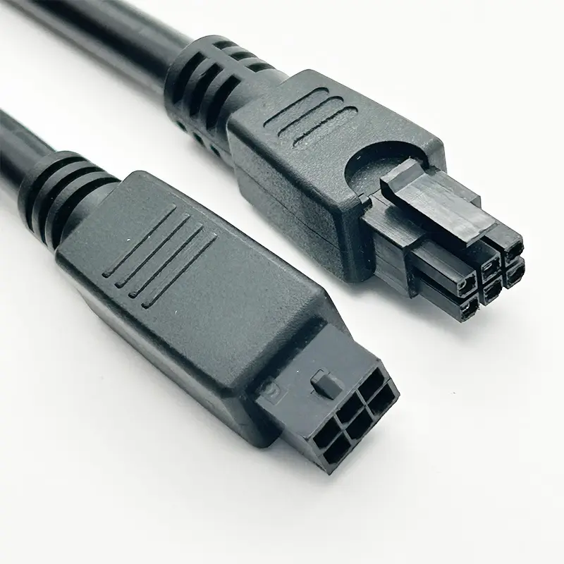
Cable overmolding is a manufacturing process in which a molded material is formed around a terminated cable, connector, sensor, switch, or another insert. The finished molded body can protect the termination and create strain relief, gripping features, keys, labels, or a defined external shape.
The process is not one universal recipe. A factory may use a single outer mold, an inner pre-mold plus an outer mold, low-pressure molding, or another method depending on the connector, termination, cable, material, and performance requirements.
The cable overmolding process in seven steps
Step 1: Requirements review
The factory needs the electrical drawing, pinout, cable specification, connector details, finished dimensions, quantity, and application environment. Requirements such as pull force, sealing, flex life, chemical resistance, temperature, and appearance should be expressed as measurable acceptance criteria.
At this stage, Zeakka reviews the information for missing details and matches the project with factories that have suitable cable-assembly and molding capability.
Step 2: Material and process selection
The selected factory reviews the compatibility of the connector housing, cable jacket, inner-mold material, and outer-mold material. PVC, TPU, TPE, polyamide, and silicone are broad material families; the exact grade determines hardness, processing temperature, flexibility, chemical resistance, color, and compliance.
Material suitability should be confirmed with the factory and material documentation. Do not assume that two materials will bond merely because both can be molded.
Step 3: Cable preparation and termination
The cable is cut, stripped, crimped or soldered, and assembled according to the approved drawing. Pin location, strip length, conductor damage, crimp condition, and terminal seating are checked before the termination becomes inaccessible inside the molded body.
Step 4: Pre-mold or inner mold when required
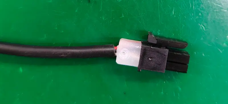
An inner mold can hold delicate terminations in position, fill internal space, and protect the assembly from the pressure and temperature of the outer molding operation. Not every design requires one, so this is a design decision rather than a universal quality rule.
Step 5: Outer overmolding
The prepared assembly is placed in the mold, the cable and insert are located, and the selected material is injected or transferred into the cavity. Gate position, venting, temperature, pressure, and cycle time affect fill, flash, sink marks, voids, cable damage, and final dimensions.
Step 6: Trimming and visual inspection
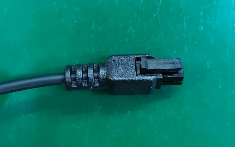
After cooling and removal from the tool, excess material is trimmed. Inspectors check the surface, parting line, cable position, connector interface, color, markings, and specified dimensions. Cosmetic acceptance limits should be agreed before production when appearance is critical.
Step 7: Electrical and project-specific testing
Every cable harness coordinated by Zeakka is tested for continuity and short circuits. Pull-force testing is sampled. Other checks—such as hi-pot, insulation resistance, dimensional inspection, immersion, pressure, vacuum, temperature cycling, flex, or functional testing—are added only when defined and agreed for the project.
Common process risks and how to address them
| Risk | Possible cause | Useful preventive action |
|---|---|---|
| Cable or terminal movement | Inadequate location, injection pressure, or missing inner support | Review fixture and inner-mold design; inspect pinout after molding |
| Flash or incomplete fill | Tool fit, venting, gate, pressure, or temperature | Approve first samples and define cosmetic limits |
| Jacket separation | Poor material compatibility or surface condition | Confirm material grades and validate the finished interface |
| Cable damage | Excessive stripping, heat, pressure, or sharp geometry | Inspect conductors and run electrical tests after molding |
| Poor strain relief | Exit geometry or material hardness unsuitable for the bend | Define pull or flex requirements and validate samples |
| Leakage | Unsealed interfaces, voids, material mismatch, or unsuitable design | Define the required IP or leakage test and test the actual configuration |
How to specify quality without overclaiming
Terms such as “waterproof,” “rugged,” and “high reliability” are not complete specifications. Convert them into requirements a supplier can quote and test:
- required IP test and product condition;
- pull direction, force, hold time, and allowed movement;
- flex angle, load, rate, and number of cycles;
- operating and storage temperature;
- chemicals, oils, cleaners, or UV exposure;
- electrical test voltage and acceptance limits;
- critical dimensions and sampling plan;
- report, photo, or traceability requirements.
An overmolded cable may be capable of meeting demanding requirements, but performance must be designed and validated for the particular assembly.
Tooling, samples, and MOQ
New external geometry normally requires tooling. Tool type, number of cavities, expected volume, material, tolerances, and surface finish affect the quotation and lead time. Zeakka therefore quotes overmolded sample timing by project rather than promising a universal 3–7 day sample time.
Typical custom cable-assembly MOQs are 200–1,000 pieces. A factory may require more when a special connector, cable, resin color, or material purchase has a higher minimum.
Questions to ask before approving a supplier
- Has the factory reviewed the connector, cable jacket, and material combination?
- Is an inner mold required, and why?
- Which dimensions and cosmetic points will be inspected?
- Which electrical tests apply to every harness?
- What pull, sealing, or environmental tests are included?
- Who owns the mold, and how are revisions handled?
- What records, photos, or reports can be provided?
- What happens if the first samples do not meet the agreed criteria?
Zeakka’s role
Zeakka is not the molding factory. We review the drawing and application, compare suitable factory quotations, coordinate technical questions and samples, follow production, and help resolve quality issues. This is useful when one RFQ contains different cable types or when the correct process requires more than one specialist supplier.
For a project review, send your drawing, connector and cable references, quantity, and required tests through the RFQ form. Detailed quotations typically take 1–5 business days after the specification is clear.
Share this article
Help others discover this content