technical

Overmolded Connector: Complete Guide to Custom Cable Assembly Design, Cost & MOQ

June 24, 2026
12 min read
Zeakka Supply Chain Team
Overmolded Connector: Complete Guide to Custom Cable Assembly Design, Cost & MOQ

1.Introduction: Overcoming Cable Failures in Harsh Environments

In industrial automation, outdoor sensor networks, smart home devices, and renewable energy systems, interconnect systems are constantly subjected to punishing mechanical stress, moisture ingress, dust, and continuous vibration. Standard mechanical cable assemblies frequently fail at their weakest point: the junction where the wire meets the connector contact. This leads to intermittent signal loss, wire pull-out, or short circuits due to water penetration. When field reliability is non-negotiable, custom overmolded cable assemblies provide the ultimate protection.

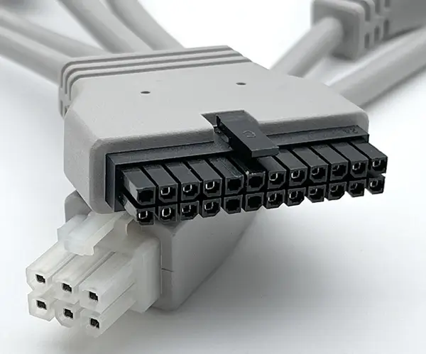
Overmolding is not merely sliding a plastic boot over a connector; it is an injection molding process that structurally fuses the cable jacket, strain relief, and connector housing into a single, unified, airtight component. This encapsulation permanently seals internal crimps and solders from environmental degradation.

For Original Equipment Manufacturers (OEMs) and hardware startups, the decision to transition to overmolded interconnects usually comes down to a classic engineering trade-off: superior protection versus upfront tooling investments. This technical guide delivers a practical framework to optimize your overmolding designs, evaluate material performance, drastically lower Bill of Materials (BOM) costs using reliable connector alternatives, and bypass prohibitive Minimum Order Quantity (MOQ) restrictions.

2.Decision Matrix: Why Choose Overmolded Over Standard Assemblies?

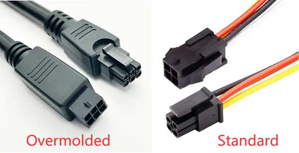
overmolded vs standar cable assembly

Before allocating engineering resources to custom tooling, it is vital to compare standard mechanical backshells against overmolded solutions across primary operating parameters:

FeatureStandard Cable AssemblyCustom Overmolded Cable Assembly
Ingress Protection (IP Rating)Poor to moderate. Susceptible to capillary moisture ingress through backshells and micro-gaps.Excellent. Easily achieves true IP67 waterproof cable assembly or IP68 ratings via absolute mechanical sealing.
Strain Relief & Flex LifeRelies on external slip-on boots or heat-shrink tubing. High localized bending stress often causes conductor fatigue.360-degree integrated strain relief. Gradually dissipates bending stresses across the cable body to maximize flex life.
Mechanical & Shock ResistanceInternal terminal retention relies purely on plastic connector latches. Severe vibration can back out pins.Internal contacts are completely encapsulated in solid resin. Eliminates pin back-out and resists extreme impact.
Aesthetics & BrandingStandard commercial appearance. Bulky, off-the-shelf profiles with limited geometric flexibility.Streamlined, professional, industrial look. Fully customizable colors, geometries, and integrated company logos.

3.Key Design Considerations for Hardware Engineers

Achieving a reliable overmolded interconnect requires clear alignment between initial electrical layouts and injection molding parameters. When providing technical documentation to a cable assembly manufacturer, focus on these critical elements:

Strain Relief (SR) Geometry and Flex Life

The transition zone between the rigid connector and the flexible cable jacket must be carefully managed to prevent mechanical stress concentration. A solid overmold creates a sharp stress riser at the exit point. To extend the assembly's flex life, engineers utilize segmented, slotted, or multi-tiered "segmented ribs" (mesh strain relief). Slotted geometries allow the strain relief to bend progressively, distributing the arc radius over a larger linear distance. For rigid applications where axial pull-out resistance is the priority, a solid, tapered strain relief profile is preferred.

Material Selection: Balancing Environment and Budget

The choice of overmold resin must match the chemical, thermal, and mechanical profile of your application:

  • Polyvinyl Chloride (PVC): The most cost-effective and common material. Excellent for general-purpose applications, indoor consumer electronics, and light industrial settings. Offers decent flame retardancy and chemical resistance but hardens in extreme cold.
  • Thermoplastic Polyurethane / Polyurethane (TPU/PUR): The gold standard for harsh industrial automation, robotics, and outdoor environments. TPU exhibits exceptional tensile strength, superior abrasion resistance, high flex-life memory, and excellent resistance to oils, solvents, and environmental weathering.
  • Thermoplastic Elastomers (TPE): Provides a rubber-like feel with exceptional flexibility over wide temperature ranges. Highly resistant to UV radiation and ozone, making it perfect for exposed green-energy installations.

The Necessity of Pre-Molding (Inner Mold) vs. Overmolding (Outer Mold)

A frequent error in custom overmolding is attempting a single-stage injection over delicate internal wires. High injection molding pressures (often exceeding several hundred PSI) can easily displace crimped terminals, twist fine-gauge wires, or distort thin plastic connector walls.

Not Molded

To avoid these failure modes, professional manufacturing utilizes a two-stage process:

  1. Pre-Molding (Inner Mold): A low-pressure injection using an economical material (such as low-density polyethylene or polyamide) encapsulates the soldered or crimped wire terminations. This physically locks the pinout geometry and acts as a mechanical shield. inner Mold

  2. Overmolding (Outer Mold): The pre-molded assembly is transferred to the final cavity, where the outer cosmetic and protective resin (TPU or PVC) is injected to form the final exterior body, sealing accents, and strain relief. Outer Mold

DFM Tip: Matching Overmold Resins to Cable Jackets To ensure a watertight hermetic seal, the outer overmold material must thermally bond with the cable jacket. For example, a PVC overmold will form an excellent molecular bond with a PVC jacket because their melting temperatures align. However, overmolding a PVC resin onto a Teflon (PTFE) or Silicone jacket will not form a chemical bond, resulting in an unsealed joint that relies purely on mechanical friction. Always specify compatible jacket and overmold materials during Design for Manufacturability (DFM) reviews.

4.How to Drastically Reduce Costs in Overmolded Cable Projects

Custom overmolding projects carry a reputation for high initialization costs due to custom tooling. However, procurement teams can implement strategic cost-reduction methods without compromising structural or electrical integrity.

1. Leverage Connector Alternatives (The Invisible BOM Saver)

In an overmolded design, the internal connector housing and terminal contacts are completely encapsulated within the solidified resin. Once the outer mold is shot, the brand name printed on the internal plastic housing becomes entirely irrelevant to the end-user. Demanding original Japanese or American brands like JST or Molex for these hidden, encapsulated internal components adds massive premiums to your Bill of Materials (BOM) and introduces long supply chain lead times. Utilizing a verified, high-quality JST connector alternative or a Molex connector equivalent from a trusted manufacturer like Zeakka allows you to bypass brand markups. These alternatives utilize identical pitch sizes, base alloys, and plating thicknesses, delivering identical electrical conductivity and crimp retention force at a fraction of the component cost.

2. Tooling Optimization: Aluminum vs. Hardened Steel Molds

Tooling expenses can be aligned directly with your actual production volumes:

  • Modular Aluminum Tooling (Soft Molds): Ideal for hardware startups, small-to-medium enterprises (SMEs), and low-volume initial production runs (100 to 5,000 units). Aluminum molds cost significantly less than steel, are machined much faster (cutting lead times by weeks), and easily withstand thousands of injection cycles before wearing out.
  • Hardened Steel Molds (Hard Molds): Reserved for high-volume mass production (50,000+ units). While upfront costs are high, steel offers unmatched geometric stability over hundreds of thousands of cycles, driving down the amortized cost per unit over multi-year lifecycles.

3. Consolidated, One-Stop Sourcing

Fragmenting your supply chain by sourcing raw wire from Vendor A, alternative connectors from Vendor B, and hiring Factory C to perform the injection molding introduces massive communication overhead, multi-layered logistics costs, and finger-pointing if a quality issue arises. Partnering with a comprehensive, vertically integrated manufacturer that controls the process from wire extrusion and terminal stamping to dual-stage overmolding eliminates auxiliary logistical fees and ensures uniform quality control under a single roof.

5.Navigating MOQs: A Flexible Guide for SMEs and Startups

Traditional tier-1 wire harness contract manufacturers are built for high-volume consumer electronics or automotive production lines. Consequently, they enforce strict Minimum Order Quantities (MOQs) of 5,000 to 10,000 units per build configuration. For small-to-medium enterprises, field-testing a new product or scaling a specialized industrial machine line makes these MOQs financially unviable, trapping valuable capital in dead inventory.

Zeakka solves this bottleneck through high-flexibility, low-volume manufacturing workflows. We understand that new hardware platforms require agile iteration. By utilizing modular mold bases-where only the cavity insert is custom-machined while the master mold base is shared-we radically lower the economic barrier to entry. This enables cost-effective production runs starting as low as a few hundred units, letting startups validate their designs in the field before scaling into high-volume production smoothly.

6.The Custom Overmolding Manufacturing Workflow

To ensure total transparency and perfect alignment between drawing files and final physical components, the contract manufacturing process should follow a strict, milestone-driven lifecycle:

Step 1Technical & Environmental Evaluation
Review of operational variables, including mechanical pull-forces, chemical exposures, temperature ranges, and IP waterproofing specifications.
Step 23D CAD Modeling & DFM Review
Generation of precise 3D drawings of the overmold shell, detailing strain relief rib profiles, gate locations, and internal terminal orientations to ensure optimal resin flow.
Step 3Prototype Tooling & Mold Fabrication
Precision CNC machining or EDM cutting of mold cavity plates based on the approved 3D design documentation.

overmolded connector tooling

Step 4First Article Inspection (FAI) & Sample Sign-Off
Production of an initial physical sample batch. These parts undergo comprehensive testing-including pre-shipment continuity testing hi-pot insulation tests, and physical pull-tests and are shipped to the customer for structural sign-off.
Step 5Mass Production & Strict End-of-Line Quality Assurance
Full production batch injection utilizing automated molding machines, backed by 100% automated electrical pinout verification and cosmetic inspections.
<style> .video-container { position: relative; width: 100%; padding-bottom: 56.25%; /* 16:9 比例 */ height: 0; overflow: hidden; margin: 20px 0; /* 给视频上下留点间距 */ } .video-container iframe { position: absolute; top: 0; left: 0; width: 100%; height: 100%; } </style> <div class="video-container"> <iframe src="https://www.youtube.com/embed/ipniNfVkcKg" title="Cable Overmolding Process" frameborder="0" allow="accelerometer; autoplay; clipboard-write; encrypted-media; gyroscope; picture-in-picture; web-share" allowfullscreen> </iframe> </div>

7.Frequently Asked Questions (FAQ)

Q1:What is the typical lead time for custom overmold tooling and initial samples?
For standard low-volume projects utilizing aluminum inserts or soft tooling, the design-to-sample lead time typically ranges from 2 to 3 weeks. High-volume hardened steel multi-cavity tooling generally requires 4 to 6 weeks for complete fabrication and testing.
Q2:Can we mold our custom corporate logo or unique geometric features directly onto the connector?
Yes, absolutely. By incorporating custom CNC engraving into the mold cavity block, we can emboss or deboss your company logo, brand name, pinout numbers, or directional alignment arrows directly onto the exterior skin of the overmolded connector.
Q3:How do Zeakka's connector alternatives ensure the same long-term reliability as original JST or Molex components?
Our custom connector alternatives are manufactured using high-grade phosphor bronze or brass base metals with precise gold or tin plating thickness, matching original manufacturer technical specifications. Every batch undergoes rigorous quality checks, terminal retention analysis, and strict pre-shipment continuity testing to guarantee drop-in compatibility and equivalent mechanical lifecycles.
Q4:What is the minimum order quantity (MOQ) at Zeakka for a fully custom overmolded cable assembly?
Unlike tier-1 suppliers that mandate thousands of units, Zeakka supports agile engineering teams with low MOQ minimums, often starting at 100 to 500 pieces depending on the complexity of the custom overmold tooling and wire specifications.
Q5:When should I choose TPU over PVC for my outer overmold resin?
Choose TPU if your cable assembly will face continuous robotic bending, exposure to industrial oils/coolants, or abrasive mechanical surfaces. Opt for PVC if the application is static, used indoors or sheltered environments, and minimizing unit cost is your primary driver.

8.Conclusion: Partner with a Flexible Supply Chain Expert

Transitioning your product line to custom overmolded cable assemblies and connectors dramatically enhances your equipment's field performance, reduces warranty claims, and delivers a polished, premium aesthetic to your end customers. By applying strategic DFM choices, leveraging cost-efficient aluminum tooling, and utilizing reliable connector equivalents, SMEs can achieve superior interconnect performance without exceeding their target budgets.

At Zeakka, we specialize in removing the traditional friction points of custom cable procurement. We serve as your flexible supply chain partner, providing engineering-backed DFM insights, exceptionally competitive custom tooling setups, and low MOQ support designed specifically to help growing companies scale smoothly.

Ready to Optimize Your Custom Interconnect Project? Get a comprehensive engineering drawing review and an optimized, transparent quotation within 24 hours. Let our experts show you how to reduce BOM costs while maximizing field reliability. Email your BOM and 24D/3D CAD drawings directly to: sales@zeakka.com

Share this article

Help others discover this content

Ready to Optimize Your Interconnect Design?

Our engineering team is ready to help you implement these best practices in your next project.