
JST 2.0 mm Connectors: Choose Between PH, PA, PHD and PUD
Table of Contents
Four families at a glance
The same 2.0 mm pitch can lead to different mating interfaces.
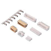
PH
Single row
Friction retention
Catalog photo
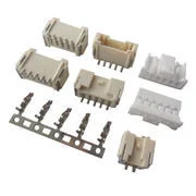
PA
Single row
Secure locking
Catalog photo
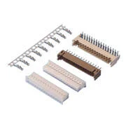
PHD
Dual row
Friction retention
Catalog photo
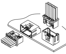
PUD
Dual row
Secure locking
Catalog drawing
A request for a “JST 2.0 mm connector” does not identify one mating interface. PH, PA, PHD and PUD share a nominal pitch, but differ in row arrangement, retention and component selection. Start with the equipment-side connector when replacing an existing harness; start with the installed envelope and connection requirements when designing a new board.
This guide is a family-selection map. It links to the existing pairwise comparisons and Zeakka's alternative-component pages so that an initial search can become a specific drawing review.
Four families, two first decisions
The table summarizes the original JST family profiles, not an interchangeability list or a statement of Zeakka stock. Mounting and entry options belong to particular part numbers and circuit counts; do not combine every option in a family description into a hypothetical orderable part.
Scroll horizontally to read all columns.
| Family | Mating rows | Retention in JST's family profile | PCB mounting listed by JST | Next review |
|---|---|---|---|---|
| PH | Single row | Friction lock | Through-hole and SMT | Compact single-row interface; confirm exact housing and header |
| PA | Single row | Secure locking configurations | Through-hole and SMT | Check latch, release access and the selected PA configuration |
| PHD | Dual row | Friction lock | Through-hole | Check both rows, terminal reference and PCB layout |
| PUD | Dual row | Secure locking configurations | Through-hole and SMT | Check lock arrangement, release access and exact header footprint |
Sources: original JST PH, PA, PHD and PUD product profiles. These original-family descriptions do not transfer ratings or approvals to another manufacturer's alternative.
Replacing a harness: identify the fixed interface first
If the PCB is already designed, the mounted header constrains the choice. Obtain its exact reference and drawing. A nominal 2.0 mm measurement helps narrow the search, but does not establish the family or the mating housing.
Count cavities, including unused positions. Record one row or two, the latch or friction-retention features, polarization and the mating-face orientation. For pitch, measure several adjacent center-to-center intervals within one row and divide by the number of intervals. Keep row-to-row spacing as a separate dimension. Do not divide a dual-row connector's overall width by its total circuit count.
Use the common JST types and identification guide if the interface is unknown. If a component cannot be identified confidently, send its dimensions, equipment-side reference if available and clear photographs for review. Do not force a near-fitting housing onto the board connector to determine the family.
Single row: when the comparison is PH versus PA
PH and PA both offer single-row 2.0 mm interfaces. The first useful distinction is retention and the complete mating geometry, rather than an assumption that one is merely an upgraded version of the other. A locking arrangement also needs room for engagement and the specified release motion.
For a new board, compare the selected housing/header pair, mated height, cable exit, release access and available footprint. For an existing PH interface, selecting PA usually means reviewing a different connection system rather than changing only the loose housing.
The PA vs PH comparison covers that pair in more detail. Browse PH alternative components or PA alternative components after establishing which interface you need. The component pages are candidate entry points; exact compatibility remains subject to drawing and sample review.
Dual row: distinguish PHD from PUD
PHD and PUD place contacts in two rows at a nominal 2.0 mm pitch. JST lists friction retention for PHD and secure locking arrangements for PUD. Its current profiles list through-hole mounting for PHD and through-hole plus SMT options for PUD. Confirm the exact selected header instead of treating this family-level summary as a complete variant matrix.
For a new design, compare the required contact count with the full installed envelope. Reserve space around a PUD latch for operation and check whether its position conflicts with adjacent components or the enclosure. Compare the PCB drawings directly: equal nominal pitch does not establish equal row spacing, hold-down locations, hole pattern, pads or housing outline.
For a replacement, keep the existing header reference as the starting point. A PUD housing is not a substitute for PHD merely because both descriptions say “dual-row 2.0 mm.” Check the entire mating pair and contacts. Shared-looking contact features are not evidence of a permitted mixed assembly.
See PHD versus PH for the single-row/dual-row distinction, or review PHD alternative components and PUD alternative components for a sourcing discussion.
Rows, solder mounting and mating direction are separate choices
Single-row versus dual-row describes the mating contact arrangement. Through-hole versus SMT describes attachment to the PCB. Top entry versus side entry describes how the cable-side connector approaches the header. A bent lead alone does not tell you all three.
Specify these independently and then verify that the selected part number actually supplies the combination. Include the complete mated connector and wire bend in the space review, not just the bare header. The through-hole vs SMT guide and vertical vs right-angle guide explain those two decisions separately.
Keep pin count separate from the wiring map
An eight-position dual-row housing has eight cavity positions even if only six are populated. The wiring document must show which positions are occupied and which are intentionally empty. It must also state the view: looking into the mating face is different from looking at the wire-entry side.
For an illustrative eight-position harness with two unused cavities, record all eight cavity identifiers using the manufacturer's numbering convention, mark the two unused ones and map each of the six populated positions to its destination. This is a documentation example, not a proposed pinout. Do not assume alternate numbering runs across rows or along each row; verify it against the actual drawing.
A color list alone cannot define this map. Use the cable assembly connection-list template to document endpoints, empty positions and drawing revision.
What a useful 2.0 mm connector RFQ contains
Scroll horizontally to read all columns.
| Required input | What to provide |
|---|---|
| Fixed mating interface | Exact equipment-side part and drawing revision, or identification evidence |
| Scope | Loose alternative components, pre-crimped leads or a finished cable assembly |
| Selected family and parts | Housing, terminal and header references; identify proposed alternatives explicitly |
| Position map | Total cavities, populated positions, view direction and endpoint-to-endpoint wiring |
| Wire and routing | Conductor size/construction, insulation diameter, length datum and tolerance, exit route |
| Service conditions | Actual electrical load, local temperature, movement and required verification |
| Purchase plan | Sample quantity, production quantity, forecast and documentation requirements |
An original-family rating is not an assembly rating. Obtain the proposed component's documentation and assess the selected wire, populated circuits and operating conditions. Do not transfer a current value from PH to PA or from an original JST part to an unbranded alternative because pitch matches.
Zeakka is a trading and sourcing partner. Request a connector-alternative review for component references, or use the custom PH cable assembly page for a finished PH harness. For another family or an uncertain interface, send the project information. The listed families are sourcing references, not an assertion that every configuration is available or interchangeable.
Frequently asked questions
Are all JST 2.0 mm connectors compatible?
No. Pitch is only one dimension. Confirm the family, housing/header pair, contacts, retention, polarization and PCB layout for the specific configuration.
Is PHD simply a double-row PH housing?
It is a separate connector family. Do not reuse a PH contact, header or wiring assumption without documentation for the selected PHD assembly.
Should I choose PUD whenever locking is required?
PUD is one dual-row family to review when secure retention is a requirement. Its geometry, release access, available part variants and application evidence still need to suit the design. A family name alone does not establish a vibration qualification.
Can I order by a photograph and pin count?
They help initial identification. A controlled order also needs the exact interface, dimensions, component references and relevant performance requirements. Confirm the proposal before production.
Share this article
Help others discover this content