
How to Specify a Cable Assembly from a Physical Sample
Table of Contents
A physical cable assembly can explain an interface that is difficult to describe in an email. It can also hide decisions that matter to the replacement: an unmarked wire specification, a damaged latch, an undocumented repair or a length that changed during service.
Treat the sample as evidence for a proposed specification. Before asking a supplier to reproduce it, agree which features must be preserved, which require investigation and which the customer wants to change. Provide only samples and design information you are authorized to share or reproduce.
Turn sample observations into a controlled specification
Keep measured observations, unresolved requirements and approval evidence in separate records.
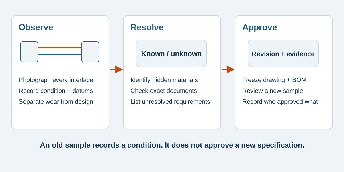
Conceptual illustration. Fictional examples are not approved product configurations, tooling instructions or inspection results.
Decide what the sample represents
Give each sample a unique identifier. Record whether it is an unused approved assembly, an early prototype, a field return or a third-party reference. Include its known assembly revision and history. An aged field return can show the installed route while providing a poor reference for original dimensions or material condition.
State the intended request explicitly: exact construction where verified, an electrically equivalent proposal subject to approval, or a revised assembly for a new enclosure. These requests require different decisions. If only one sample exists, agree what examination is permitted before shipping it; cutting, sectioning or terminal extraction may prevent its return in the original condition.
Keep ownership and handling instructions with the sample record. Specify return requirements, whether destructive examination is authorized, and who can approve a proposed construction. Photograph the sample before dispatch so arrival damage is distinguishable from its original condition.
Separate observation, identification and requirement
Use a three-column record rather than describing every visible feature as a specification.
Scroll sideways to read all columns.
| Topic | What the sample can show | What still needs confirmation |
|---|---|---|
| Connector | Markings, cavity count, keying features and visible condition | Exact housing, terminal and mating references; permitted alternatives |
| Wire | Legible jacket printing, colors and external diameter | Full wire construction, conductor details, material identity and required ratings |
| Circuit | Connections established by an agreed examination method | Approved cavity numbering, viewing direction and intended circuit assignment |
| Length | A dimension measured using stated endpoints and setup | Required nominal value, datum, tolerance and installed routing allowance |
| Protection | Position and visible form of sleeve, tape or strain relief | Material specification, required coverage and application requirements |
| Quality | Visible condition and recorded examination results | Acceptance criteria, evidence requirements and production controls |
A molded family marking is a useful identification clue. It does not by itself establish the full orderable reference or the provenance of the component. Use the connector identification worksheet to assemble the evidence without guessing a part number.
Preserve the circuit before disturbing the construction
Capture both connector faces and label the viewing direction. Mark the orientation feature and cavity references on the record. A photograph from the wire-entry side can reverse the apparent left-to-right order seen from the mating face.
Request a numbered connection list linked to those views. Where continuity examination is appropriate, agree the method, access points and handling requirements; do not improvise a probe that can spread a contact. Record the result as a connection observed on sample S-01, then obtain approval of the intended production circuit. A field repair or wiring error should not silently become the new design.
For JST components, the handling precautions, under precautions for SMT products, warn against inserting items other than the applicable mating part during continuity or miswiring checks. Use the relevant product instructions for the actual connector. This is a handling boundary, not a universal test procedure.
Convert measurements into proposed dimensions
For each length, record the endpoints, whether the assembly is straightened or installed, and how branches are positioned. A single measurement is an observation from one item; it does not establish the production tolerance.
If the sample is fitted around a bracket, document the installed route as well as the free assembly. Identify the enclosure and mating-board revisions. Ask the customer to confirm the reach, slack, fastening positions and access needed for assembly or servicing. Do not infer a universal bend radius from the shape of an old cable.
The cable assembly drawing guide explains how to express the agreed dimensions and circuit in a controlled drawing. This sample review supplies the evidence and open questions that the drawing must resolve.
A fictional sample-to-specification record
The following example is invented. EX-S204 and its component codes are internal illustrations, not orderable references or an approved Zeakka construction.
A customer sends sample S-01 for EX-S204. It has two connectors and four wires. The customer wants the same electrical connection but a longer branch for enclosure revision E2. No material certificate or approved drawing accompanies it.
Scroll sideways to read all columns.
| Record item | Observation or request | Proposed disposition |
|---|---|---|
| Main length | S-01 measures 245 mm between recorded mating-face datums | Customer to approve a nominal dimension and tolerance; do not copy 245 mm as a tolerance-free requirement |
| Branch B | Sample route is too short for E2 | Customer to review a revised route in E2 before releasing the new dimension |
| Contact identity | Housing marking is visible; contact reference unknown | Obtain identification evidence and applicable documentation before confirming the BOM |
| Wire | Jacket shows a partial code | Resolve the complete wire specification; do not assign a rating from color or diameter |
| Circuit 3 | Observed connection differs from the customer's sketch | Hold circuit release until the customer resolves the conflict |
| Sample handling | S-01 must be returned intact | No cutting or terminal extraction without separate authorization |
A useful quotation can state assumptions and unresolved costs while this record remains open. A production release cannot rely on an unresolved circuit conflict simply because the supplier has a physical example.
Review proposed differences before sampling
Create a difference list covering each proposed departure from the sample: part identity, wire construction, dimension, protection, label or process. State why the departure is proposed, what evidence is available and who approves it. An unbranded alternative requires evidence for its own construction; original-brand ratings do not automatically transfer.
Identify prototype-only substitutions separately from the intended production BOM. Otherwise a temporary component selected to test fit may become an accidental purchasing specification. Link sample labels and inspection records to the proposed drawing and BOM revision.
When the new assembly arrives, use the sample approval checklist for the approval decision. Preserve the original reference, the proposed specification and the evaluated sample as separate records.
Frequently asked questions
Can a supplier quote from photos before receiving the sample?
Photos and a requirements summary can support an initial review. Identify any quotation assumptions and what remains subject to physical examination, part identification or customer approval. Do not treat an indicative quotation as confirmation of an exact construction.
Does matching the sample prove equivalent electrical performance?
No. External resemblance does not establish conductor material, plating, insulation properties or performance under the intended conditions. Define the required performance and supporting evidence separately from appearance.
Should the only reference sample be dismantled?
Agree this before examination. If the sample must remain intact, identify what can be learned without changing it and which questions need another authorized specimen or documentation. Destructive examination should have a named purpose and permission.
Can Zeakka supply an original branded connector separately?
Zeakka coordinates sourcing for cable assemblies. Original JST or Molex components are considered within finished assemblies on a project-specific basis, with supply confirmation. They are not offered as loose original components.
Send the sample with its open-question record
Contact Zeakka with authorized sample photos, its history, the intended equipment, a connection sketch and the changes you need. State whether the sample may be altered or must be returned intact. Zeakka can coordinate supplier review around that record; exact identification, manufacturing feasibility and any required examination remain subject to project confirmation and customer approval.
Share this article
Help others discover this content